Verry nice pictures!
is it possible that you limited the Amps with your measuringsetup?
Verry nice pictures!
is it possible that you limited the Amps with your measuringsetup?
Thanks. If anyone need to better see the writing on the components I have some other where its easier to read.
Not too long ago the power supply was used by a company working with electronics. My brother checked it too, and it was accurate according to a quick test (he works with electronics). I have not made proper wires for it. Although a potentially tiny bit of voltage sag does not really matter since the driver is properly regulated. (same output if you have everything between 6v to 8,4v input).
The amp meter is accurate, and there is not much wires between LED and driver. All of which are oversized. And again.. Output is regulated.
Measured emitter amps also goes hand in hand with the rated output.
Anything surprising to you?? If anything is off, Id guess its more likely it was me who did not see correctly from the analog reading. Numbers are pretty much just like I expected them to be.
Awesome, thanks a lot for the photos and info.
The Microchip MCU looks very programmable, anyone in for any ramping/customizable user modes?
Nice tear down, testing and mod info. That light sure looks like it has lots of potential. That MCU looks like it’s probably right up tterev3’s alley.
Nice light and teardown ![]() Wonders why you said: ” I added another R030. Do not do this. ” >)
Wonders why you said: ” I added another R030. Do not do this. ” >)
i was just remembering that I (very often) can’t see the woods because of that many trees… ![]()
did you measure the vf?
:beer:
I just want more output.. 0:) For a thrower of this size I dont need all the fancy ramping (DrJones awesomeness) that I would take on a more general use light. TK61 serves one purpose to me. Maximum throw. UI is not that imporant. When that is said. I actually think the TK61 UI is quite nice. Especially for this type of light. Its even got a nice momentary feature now. The only thing I miss is the ability to cycle backwards through the modes. I even love the crazy strobe. It changes frequency. Which looks awesome. :D
All of my other throwers have more output then this light. And TK61 is the largest thrower that could easier shed off more heat. Even several of my smaller lights are driven harder than the R030 resistor modded TK61.
NEEDS MOARR POWAH! :D
[quote=ImA4Wheelr] Nice tear down, testing and mod info. That light sure looks like it has lots of potential. That MCU looks like it's probably right up tterev3's alley. [/quote]
When will you deliver HX-1175B with custom UI suited for electronic switches? Preferably two electronic switches. 0:) Are these just dreams, or could they become real? You probably know what backup driver I have in hand for this light in case I don't get output as I want.
I think the light have potential of 700+ kcd. Im just at stage one now.
[quote=DenBarrettSAR] Nice light and teardown :) Wonders why you said: " I added another R030. *Do not do this.* " >) [/quote]
Because Turbo does not go higher. Only the lower modes. Basically you mess up mode spacing more, and low becomes higher without any increase in peak output. No purpose in doing it, unless you are into bad mode spacing.. :D
Unless someone finds out how to make Turbo increase more. It seems like a single R030 is around the max limit of what is useful to add based on what I have seen so far.
[quote=M4D M4X] did you measure the vf? [/quote]
Nope. But djozz have vF numbers here.
Great thread. One question.
I was told over 4/4.2A you risk alot with this driver. The transistor need to be replaced in order to get higher amps, or you risk alot….
Edit, i just saw you covered that part, my bad.
nice tips for one of the best single emmiter lights !
why the mcpcb is “half circle” ?
These should be the transistors that mounts the TK61 (C01C)
As you can see, the current is continuous DRAIN
3 A ~,
(I was studying modding, before you buy the flashlight, with more pictures!)
You could try to change them, the impression is SOT-23-3
strong collection of lights , and very good review. TK61 looks similar to me but i cant find to what…
Nice effort on the strip down, mod and report. You know what I believe you should do with this light so I will shut up. 
Dont know. Ask Fenix.
Not a big deal though. Its still got way way larger contact path compared to say a 20mm Noctigon.
Sorry, most of the info in the datasheet is beyond my understanding of small electronics. I should replace all (?) the C01C with what? Link for suitable replacement part?
I named some of the components on the backside too in case they were hard to see.
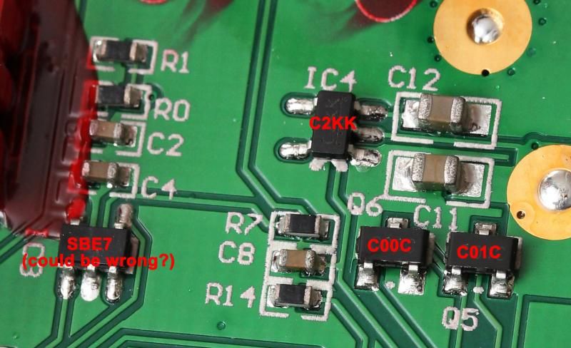
So its one C01C on the backside and three on top-side. (Top-side is towards the battery carrier.)
Its two C00C on the top-side, and one on the backside.
MT-G2?
Send it to you?
:D
This is just a hunch based on working with other drivers and not based on electrical expertise or anything else reliable. So please don’t act on it with out reliable confirmation, unless you feel like risking the driver. It appears that Q1 - Q4 on the side with the voltage sense resistors are the ones to replace. Hard to tell though with all those traces going all over the place. My understanding is that you are looking for the FETs that connect directly to the LED feed pads. Looks like you have 2 for positive and 2 for negative, but it’s hard to tell with all the traces going under component and such in those pictures.
EDIT: Looking closer, it looks like Q1 - Q3 feed the postive LED pad via the inductor. Also looks like Q5 & Q6 my by feeding the positive LED pad too, but can’t see the via’s due to inductor blocking the view. There is lot of stuff going on in that driver.
Maybe this would work well:
http://www.mouser.com/ds/2/427/si2323dds-254119.pdf
I'm not sure, it could be that it was designed
Network with pull-up + pull-down?
some N channel MOSFET should be ...
Why do not you try to test them with a multimeter to see if they are P-Channel
or N-Channel?
No video here, you should understand that!
I unfortunately do not! ;)
Hmmm, I am kind of a disappointed with plastic reflector and all that plastic that holds the switches, pill also looks wonky ![]()
Plastic reflector is more then fine, it helps with the weight and i guess a bit with the cost ![]()
Doesn’t seems to affect the performance at all.
Yes, but for this premium-priced light you would expect that fenix would put a bit more effort and made machined aluminium reflector.
Maybe I just expect/dreamed too much, because this light is on my “want it so bad” list ![]()
Even the RC40 has plastic reflector i think….
I got the TK61, the feel in hand is amazing, the buttons you mention, are the best i ever felt on any flashlight, the feedback is great. One thing i think Fenix focused more is the driver quality.
antoninodattola, you got a PM.
I don't mind the plastic reflector. As long as it works great and is well built. Lower weight, and no worry of short circuits if you have to replace with smaller mcpcb.
Would be nice to have a bit more mass below the mcpcb. But at the stock 3A current, I doubt it would matter. Only add more weight and cost.
On the stock light I would like to see 4,5A on Turbo and an easy resistor mod to 7A. 0:)