I would check into your numbers btw. You measured 2,85A at the emitter and 1200 lumen OTF stock. Those numbers does not seem to go hand in hand to me. Even if the emitter saw 3A. Would you expect 1200 lumen OTF? Seems too high compared to Cree`s own data, Match, djozz, Fenix, Selfbult, etc.. For all I know, Fenix could have gotten U3 and not mentioned it, but I doubt it. Still, would seem a bit high.
It does seem a bit high to me as well, but unfortunately the stock light I was measuring was a different copy. I never measured the one I modded beforehand, so I don't know how high it really was. I have a suspicion that the current is actually a bit higher at the emitter than what my meter says, due to the extra resistance of all the alligator clips, etc. I was using.
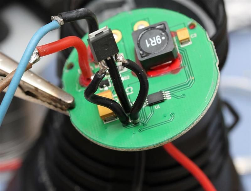
Solder a loop in (basically extend the negative lead) and clamp around it. Piece of cake and little to no extra resistance is added. On the bench, it’s easy to measure directly from the leads between the driver and emitter, no splices cuts or clips required.
Took this out last night. All I can say is that my sight was limited only by the environmental haze / dust, not by the level of light. I think I might like this one better with the dome left on but with the current cranked up, that way I get a bit wider beam. The BTU Shocker cranked up has a better beam (MUCH wider, very similar intensity) than this IMO, but this is much lighter and the runtime is much longer!
If these didn't hold up, that was going to be my next step: remote mount a 70N02. I have run several 10-15 minute torture tests and it's holding strong so far.
RMM i hope you will stock some mosfets for this light, it will be very good to have an option to buy them from your store, instead of endless searching on mouser site.
I think I may try the 70N02 and try for 6.5A-7A with the stock driver. If it blows I guess I'll have a $150 paperweight, huh? Nah, that will just motivate me to try my 7A-8A option...
If 5,8A is peak. Im already headed for my 7-8A option.
But I could try 70N02 first. Just replace/remove "C001" from Q1 and connect the 70N02 in similar fashion + further resistor mod? I can try that if you want. But if you are going to do it anyway, I could just sit back and relax get some progress done on my scratch build.
Racer, I'll let you try it first! I'm pretty busy today. I would keep the resistors the same to start with and see how the current compares. I think that at a certain point we're really going to need a larger inductor, more input capacitance, etc. to make this reliable.
No, that's the correct way. The gate charge, PWM frequency, etc. may not be suited for the 70N02. I guess we'll have to stick with stacked "tiny" FETs for now. BTW I have run this one quite a bit more and it's holding up well. I feel confident with it around 6A.
Bah...nevermind. Just realised that RaceR already tried the same basic thing in post #88. Guess it's time to order up some of the smaller ones from mouser.
Hey guys, I don't have any of the tiny mosfets but could you use this voltage regulator instead of the stacked minis?
How do you guys solder these resistors on? I was told at the local electronic store if I use a soldering iron it will fry the resistor. They said I need some kind of special heat gun?
Welcome to the twilight zone. Its called a hot air rework station I believe. But its not required. The guys (and gals) here have been doing it with soldering irons for ages. They do so daily. They dont just solder them on to new boards, they stack them.