Yeah, sorry, I didn't keep a change log for the first few changes, so i didn't want to start now ;)
I thought it might be a nice idea to move the 1u capacitor for off-time memory to a different place, between star2 and star1 (gnd).
But after some research I assume this won’t work.
According to the ATtiny13A datasheet, only PB2, PB3 (Star4), PB4 (Star3) and PB5 are an ADC Input Channel, whereas PB0 (Star2) and PB1 are not.
Does this mean only PB3 and PB4 can be used for the 1u capacitor, but not PB0?
HarleyQuin, that is what I have been assuming.
Why did you want to move the cap? When I first tried the offtime firmware I was planning on placing the cap directly between the physical Pin2 (pin that conects to Star 4) and GND. I did it, but had some other problems and ended up needing to remove the cap to reflash a couple of times - in the end I put it on the bottom between the star and GND and never put it back. So I never fit it to a flashlight while assembled that way. I’ll probably try again.
I generally do just put it on the physical star, but I have built a few lights where I wanted the entire underside to be flat so there and on the FET drivers I just reflowed it between ground and the attiny pin.
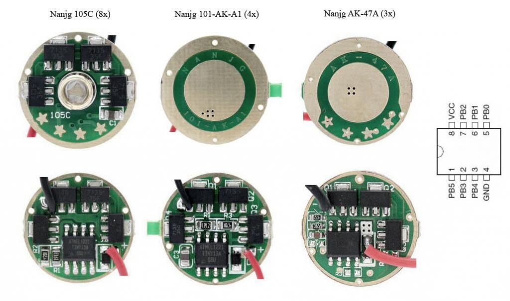
All started with the Nanjg 101-AK-A1 (4x 7135). Very nice driver for smaller lights with the advantage of being single sided, no stars to be shorted with a retaining ring, room for a large and flat spring. But, as you can see…
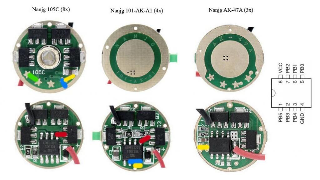
… on the 101 there are only bad places for the capacitor, a change of firmware would always need desoldering. Blue is what the firmware suggests, red would still be nicest, but that is Pin5/PB0 (Star2). Yellow is what I seem to have to end up with, using a 0805 package capacitor and changing the firmware so that Pin3/PB4 (Star3) manages the memory.
While considering I compared it to the 105C. Having too large capacitors (SMD 1210, 1206), at the blue place it will collide with the pill. Red would be similar to the place on the 101, so I thought of Star2, which is connected to Pin5/PB0. Well, the green place between Star2 and Star1 would be just perfect: easy to solder and not colliding with anything. But I think I will use a 0805 package capacitor at the yellow place on this one.
With the 47A it’s easier. Each Star has a related solder point on the component side and a GND solder point nearby (marked R2, R3 and R4). Perfect for the cap.
Perhaps someone has use for this compilation without my markings, so I might as well add it here. The 6 Nanjg pictures are from Fasttech, as are my driver.
Just follow the link behind the picture.
Thanks for the pics HarleyQuin - clear driver pictures are always an asset.
I’ve started modifying the STAR (SRK_no_ramp_1.0.c) firmware to run the DQG 26650 EDC triple light. EDIT: which is an e-switch setup with a pretty unique method for controlling modes.
Very nice wight. How does the UI work? Richard gave me a slight nudge to finally get the dual switch program written, something I've been planning on doing for months but just haven't created the time.
Glad to hear that you're working on a dual switch program! I think many modders and users would love that. With 4 easy to define user inputs (2 short and 2 long presses) you can easily do up/down and special/off. That would satisfy basically all of the things people have asked for... as long as they build a dual-button light of course.
I'm not sure what you're asking me though. The UI should be the same as your original one if I've done things correctly. I don't own one of those flashlights, so I am unable to describe the stock UI. Ahh.. I probably wasn't clear in saying "a pretty unique method for controlling modes". I meant that the driver board does not use a PWM, serial, or other conventional way of controlling the modes. They are controlled through a series of 4 pins on the MCU. You bring them up like this for the 4 modes:
none: OFF
RUN_PIN: LOW
RUN_PIN & MODE1_PIN: MEDIUM
RUN_PIN & MODE2_PIN: HIGH
RUN_PIN & MODE3_PIN: TURBO
Ahhh whoops! I misread your post thinking that the light you were using this program on had two switches. Nevermind!
I’ve got my programmer and AVR Studio 5.1 set up (thanks Comfychair for your excellent howto). I’ve been looking at the STAR 1.1 version (and a few others people have posted here) and have a quick tip for us lazy people on how to calculate the voltage levels for ramping and low voltage cut off.
In the source code this comment is the original formula: Value = (V * 4700 * 255) / (23800 * 1.1)
For me that’s just unnecessarily long. If I understand it correctly, these values are not that accurate in terms of exact voltage, so why not make the formula simple instead? Like Value = V * 45.78? It’s the same thing (well, almost the same thing. Value = V * 45.779220779220779220779220779221 would be EXACTLY the same thing).
Sorry if this has been posted, I read through this thread but didn’t see it in that case.
Also, what is the reason for this:
#ifdef MODE_TURBO
#undef MODE_HIGH
#define MODE_HIGH MODE_HIGH_W_TURBO
#endif
As you are programming the modes yourself, why would you want to do this rather than just change the MODE_HIGH to what ever you wanted in the first place? Why have a MODE_HIGH_W_TURBO? Turbo mode is not selectable by soldering stars so I see no point in doing this. If you have edited turbo mode on or off you should be capable of editing the MODE_HIGH to be want you want it to be, it is simple enough. What is the reasoning behind having this MODE_HIGH_W_TURBO?
Wait, does the attiny13a have the ability to do floating-point math? Is it actually built in or does the compiler fake it? Does it use up a bunch of extra ROM space (for fake FP-handling code) if the program includes floating-point math?
I was assuming these were integer-only.
It’s not the code itself, it’s the comments on how to calculate the value from the desired voltage I was referring to. The end value used in the actual code has to be rounded to an integer either way.
This is for when someone programs a lot of different lights, and they can just set it and forget it and only worry about enabling or disabling turbo.
I’d think that someone who programs a lot of different lights would have a lot of different source files, I know I will ![]() But I guess it’s down to personal preference…
But I guess it’s down to personal preference…
Compile-time options are generally a good thing. They almost literally make the world go around.
Normally, it’s used so that a configuration script can auto-configure a program to build and run correctly based on what it detects about the host system, and compile-time options like that were probably part of the build process for 90% of the programs on your computer. The only real difference here is that it’s a human defining the parameters instead of a script.
Got mine in wight…just gotta solder some leads to it and give it a whirl ![]()
Sweet, keep us posted. Looks like I’ll know whether my two bucks was a wasted investment long before I receive the product. ;~~)
I am changing the functionality of some of the features with the STAR 1.1 firmware and just want to make sure about what this line of code does:
PWM_LVL = modes[- -mode_idx];
This changes the PWM_LVL (output) to the level of the previous mode but does not actually change the mode itself. This means that if this line is executed while the light is on high, the output will switch to that of medium, but the light will still “think” it’s on high and remember high as current mode if switched off. Is that correct?
What are you wanting to do?