
Capacitor does an amazing job at knocking out nearly all the squeeeee caused by the 9.4kHz firmware... it's barely audible on the bench like that, installed in a light it should be totally gone. Hopefully. :~
Capacitor does an amazing job at knocking out nearly all the squeeeee caused by the 9.4kHz firmware... it's barely audible on the bench like that, installed in a light it should be totally gone. Hopefully. :~
Its my understanding and has been documented that a led in low pwm can take a higher current than it can driven fully on. I understand with amc7135 that the current is constant in all modes, but that is because they are current regulators. No matter the voltage or sag of a single li-ion, as long as the voltage is above the vf of the led at that current plus the .12v overhead for the amc7135’s, it will still give its rated current times the number of amc7135’s in any mode.
What I’m not sure about and don’t know exactly if it has been answered here, is if the battery voltage is higher in low modes, less voltage sag with a FET (its basically direct drive with modes from the attiny13). Because if it is that would mean, I’m guessing anyways, That with a higher battery voltage (less voltage sag) direct drive (FET) current would be higher in low modes. Direct drive current is all based on what voltage the supply can give and the other parasitic resistance.
ImA4Wheelr it maybe time to knock the dust off that oscilloscope. ![]()
Forgive me if the question has already been answered. :~
I can hardly understand the language being spoken in this thread but I know I can learn a lot from it if I do my homework. :~
Thanks for leading me to this thread ImA4Wheelr! ![]()
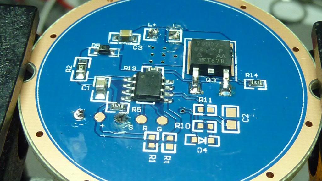
OK, I’m looking at a HX-1175b1 driver. Off memory, it looks just like the HX-1175b in the UF-T90 (SST-90 version) and what I hear is in the Lustfire 3U2?. I does have a blue top coat (instead of black) and it appears to have larger sized “voltage sense resistors” (the “b” has 1206 size). I’m wondering if the are actually “voltage sense resistors” now because of the ciruit lay out. These resistors go between the ground ring and the source pin on the DTU 06N03 FET’s. Changing these resistors directly alters current on the “b” and should on this model too. There are 2 R068 in the resistor bay. In the “b”, the driver delivered 11 amps to an MT-G2 by adding 2 R10 resistors to the bay (If I remember correctly).
So my question is. Are these resistors purely restricting current flow as opposed to being used in a “voltage sensor” circuit. I see no other connections from these resistors and the rest of the driver. Hopefully, you all can picture what I’m talking about. If I can, I will take a couple pictures tomorrow.
EDIT: For those not familar with the HX-1175b, it is a buck driver.
Exactly…a FET is more or less a “solid state switch” when the gate is activated source and drain are connected like a wire the resistance of that wire is the mOhm rating from the spec sheet…the more resistance and more current = heat generated by the chip…but it will push whatever voltage that is on the source thru to the drain, the amc7135’s are regulators the FET is a on of wire (not to insult anyones intelligence)
This isn’t particularly for you…but I too learned alot by watching this video
")
Again, not to insult anyones intelligence…but to educate {I too was mistaken on what the FET was and how it worked compared to the AMC7135}
Take pictures. Basically the sense resistors must be in the path of the current (of course you’ve already said that these are) and the buck IC must be able to see both sides: in other words if one side is GND (we assume the buck controller is on the same GND) then the other, non-GND side of the sense resistors must have a trace going to the buck IC (preferably a short trace). The buck IC needs to be able to measure voltage drop across the sense resistors.
That is my understanding too. Which means the resistors are not limiting current on their own as they could not possibly handle 11 amps of current and they would not appreciably lower voltage in a drive that can buck from 16V down to 3V. The they must be helping the driver “sense” voltage differential for controling current. It’s just not happening directly at the resistor bank. Maybe through the FET’s drain pin.
EDIT: I was replying to WarHawk. I will take some pictures and post tomorrow. Thanks guys.
Dear all
I have original 7x XML T6 torch with driver that were talking about

the light was working few minuts and stopped
I found defective FET 35N03…but I dont have it
I have 50N06 and 70N06
Can I use some of those fet? must I change some of resistors?
Thank you all for help.
best regards
svicar
I have the same driver and swapped in the 70N02, no other changes.
yes but I dont have 70N02
I have 50N06 and 70N06
can I use some of those?
thank you
Try it, it’s already broken, what’s the worst that can happen? Probably try the 70n06 first. Note the 70N02 was chosen for its extremely low RDS (on), its one of the best performing (lowest resistance) FET’s out there, so don’t expect the light to perform any better than stock from this component swap.
Helo
I put 70N06 but the performance is very bad (is better then with 35N03 defective)
what can I do? can I change the resistor? what value?
or I can buy 70N02? what about AOD510?
how many amps can I put on 7x T6 in serial?
thank you for help
AOD510 works well, it's not quite as good as the Vishay 70N02 but it's close enough.
Ok…
Now I have 70n06 that has 15mOhm internal resistance…can I put the R13 (10 Ohm) away…or I will burn something?
It depends. You're working with a blue SRK driver, like the one in the first post? Still using the stock MCU or are you using another board with an attiny13 as the controller?
If it works without the gate resistor then it's not needed. If it doesn't, it is.
The board is blue…original just the 35n03 is replaced with 70n06
Do you think that I can remove those resistor?
Why does it need to be removed? Does it work better without the gate resistor? 10 ohm is not enough to have a negative impact on the FET's switching speed, if it works just leave it there and move on to something else that matters.
The problem is that with 70n06 the performance is very very low…how to increse the current to the leds emitors? There are 7 xml t6 conected in series
The drivers in this thread are single cell (3-4.2v) direct drive, as in SkyRay King and the like. I have no idea what driver you have there and what the power source is, if it's able to power 7 LEDs in series.
Helo
I have the same torch as skyray king but the name ultrafire. It has 7 Xml t6 leds in series, driver blue like in the first pages of the forum,
batteries 4x 18650 paralel so 3.7 - 4.2v
When I turned the torch on it stopped working after few minutes. I found FET 35n03 defective so I removed it and put 70n06 ( because I dont have any other at home). Now the light is very low. What to do, to incerease the light power ( the current to the led emitors)
Thank you