Tom E - I think the problem is being able to purchase it! It seems that people are often sent something other than this driver when they attempt to order.
Hhmm - I thought this link in the OP: ebay.com/itm/5pcs-5-modes-Led-Driver-Input-3V-18V-7A for qty 5 were for the b1's -- yes, ImA4Wheelr did confirm with the seller first, but those b1's look good so far. Right? $50 is a fairly big risk of course, but of course I've lost that much on a gamble before with drivers... If I were to order 5, I'd like to use like 2-3 off the bat, or give/sell at cost, etc., and check with the seller first like he did.
It looks good to me Tom, but I'm just a hack. I think he sells individual drivers too.
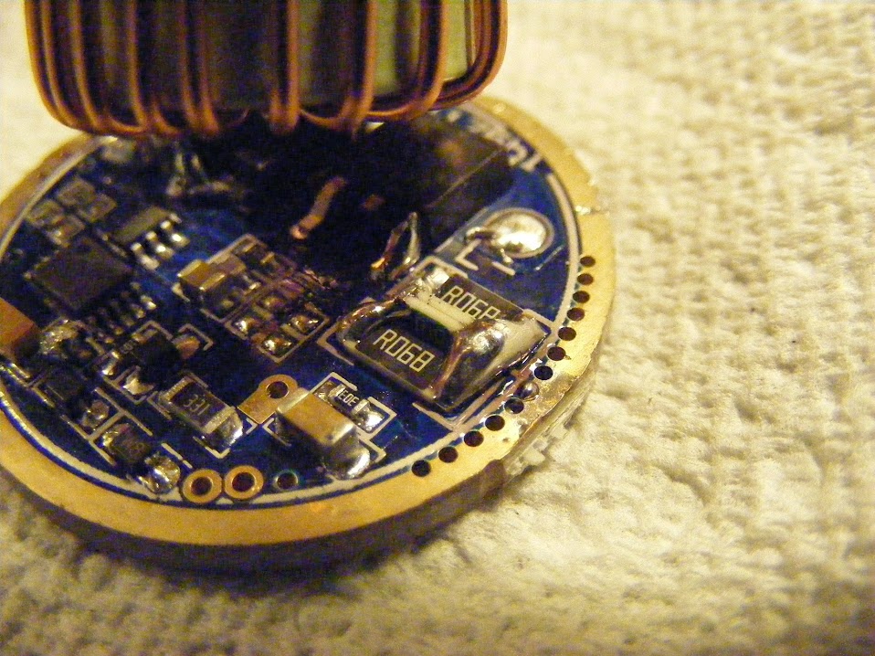
Here is what I did tonight. Removed the large diode and FET and compared the traces between the "b1's" and the "b". Every trace I can see looks identical. I tried to take photos of the "b", but the black pcb reveals very little in photos. I did get some good photos of the "b1" which I put in the beginning of the OP at full size. The toroidal inductors look identical too. Only difference I see is the FET's Source Pin resistor bay allows for much larger sized resistors, but underlying trace for both looks the same. I did not compare components though. I will try to do that tomorrow as it's late. As pointed out in the OP, I do see at resistor where there is a small capacitor on the "b".
Here are the 2 components I thought were FET's that I pulled off the "b". I can't tell if the one with the label ground off is a diode, but I think it is based on wight's analysis above.

Went ahead and swapped the FET to a 07N02 (Comfychair) FET and added 2 R10 resistors. Go 11.5amps in high mode and 5.x amps in Medium mode. There was no Low or SOS mode. Ran for a about 1 minute on high. Driver got pretty warm, but is was in free air and isn't pressed into a large brass ring like the T90 driver.
I'm sure I missed something, but I have to call it a night.
This driver with an attiny13a piggybacked would be pretty cool.
Wight, I've been searching for a long time for a good PWM dimmable synchronous buck IC...haven't found one yet that fits the bill. I have had a few ideas about converting some other board designs but as always time is an issue.
I'm thinking the large diode is going to be the weak link for very high currents. Last night after reinstalling it, heat was generated in that part of the driver (Running at 11.5 amps with 3S King Kongs). It will probably be fine if heat sinked, but it is only rated for 10 amps. I may piggy back another low voltage drop out diode on top of it for the time being. Anyone have a high current diode recommendations?
The I just found out this vendor sells this driver directly from their website too.
http://www.topledlight.com/led-driver-input-3v18v-for-phlatlight-luminus-sst90-led-light_p1235.html
What is the overall diameter of the toroid used on this driver?
Best guess is about 1 inch. I will measure tonight.
Thanks. I’m sure you realize this, but what I’m really looking for is the smallest diameter tube the toroid will fit into. So anything that can be sqeezed in doesn’t count, but measuring the shortest side also doesn’t help.
Diameter ranges .805" to .825" on the sample I measured. They're make of the typical copper wire around a rubber doughnut. So it's slightly compressible if needed. Don't forget to for the LED wires and a rubber/Kapton tape barrier (if you are like me and don't totally trust the enamel coating). Just in case, but I'm thinking you already have all that covered.
Thanks! I figure if worst comes to worst the LED wires can go through the middle of the toroid. Are you sure the doughnut is rubber & not ferrite ?
OK, I'm even more of a dufus than I thought. It must be some kind of ceramic coated/impregnated ferrite material. Magnet definitely grabs it. I take it that is needed for a magnetic field?. For some reason it felt squeezable. Guess it was just he copper wire giving way. Sorry for the mis information and thank you for catching that.
Going to crawl under a rock now.
Heheh. I’m sure I thought they were made of something else for years, the colors are misleading. ![]()
So yeah, frankly I do not have a handle on exactly what the core does, but it is there for it’s magnetic properties. It is my understanding that this is the part that ‘saturates’ under certain circumstances in our buck drivers, this causes unhealthy voltage/current spikes or maybe DD.
OK, want to splice in a Attiny13a tonight. With the meter, I get a 123Hz at the FET gate and as the top pin closest to the circle/divit on the MCU. Does it make sense that that particular pin is connected to ground via a 30,000K resistor?
Another question. I would prefer to pull the stock MCU off the board. I don't mind if I lose voltage monitoring (if it even has that). I don't think that should interfer with the bucking function. Anyone feel differently?
Here are my voltage readings (with 2S King Kongs). Pin 1 is at divot and then they count down the side and then over to the other side and then up (so clockwise).
1 -0- 10 .618V
2 4.86V 9 4.86V
3 -0- 8 4.85V
4 4.86V 7 4.86/4.87V
5 -0- 6 -0-
EDIT: Corrected pin readings.
So pin 10 can be used for voltage monitoring, if desired. I plan on pulling the MCU, and wiring an Attiny13a to pins the HX-1175b pads 8 (+ in), 3 (Grd), and 1 (PWM).
I’m having trouble figuring out exactly what’s going on.
I guess I’d just remove the MCU and then probe with the DMM to find out which pad is VCC for the MCU. Once I found that, I’d pull Pin1 high and low. If I can turn the buck circuit on and off that way then I’m good to go. Pin1 certainly looks like the PWM pin.
EDIT: As far as I can tell, neither Atmel nor Microchip have an 8-bit MCU with 10 pins.
Thanks wight. I tried what I said above without success. I soldered wires as follows:
- Attiny Pin 4 (Gnd) to HX-1175b Pad 3
- Attiny Pin 6 (PWM) to HX-1175b Pad 1, and
- Attiny Pin 8 (+ in) to HX-1175b Pad 7.
I flashed the Attiny with MiniMo.
I wish I had thought to probe the MCU pads after removing the MCU. I think I picked the wrong pad for + input as I was getting a very unstable voltage to the mcu. It would fluctuate from sub 1V to 3.3V. Could have been a bad connection.
It's late. I will take another crack at it tomorrow. I wonder if I have to have the voltage divider pin (pin 7) on the Attiny13a connected for it to work. I would think that would depend on the FW. I don't think MiniMo monitors voltage.
Yeah, I don’t think MiniMo does monitor voltage. If it did, you’d want to pull the voltage monitor pin high (connect to Vcc).
When you get back to it I imagine you should be able to easily correct the situation by finding Vcc w/ your DMM.
Note that you may get better dimming results with an extremely slow PWM freq such as what we used in the Knucklehead driver thread. I wonder if I ever got around to compiling a less heinous firmware configuration for that? Probably not. I wrote about what was wrong with the current compiles and posted the code in that thread.
Sounds like good advice. I need to check out your Buck Driver thread. It was just starting when I last perused it.
Didn't get but a few minutes to work on this tonight. Definitely got different readings without the stock HX-1175b MCU in place. Some of the pins that I read + voltage on were getting the voltage from the MCU. I don't recall the readings right now. rewired the positive feed, but it still didn't work. I should have tested the MCU before wring in to the HX-1175b. Hopefully, I get a chance to take a crack at it this weekend.