What did I change? I don’t know. I spent too much time tweaking stuff tonight.
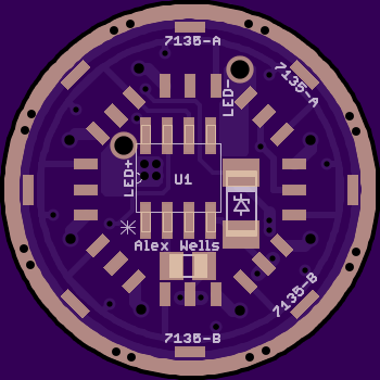
I moved the offtime cap away from the MCU. In order to move it as far as reasonably possible I had to reroute the PWM trace. The PWM trace did not have another clear path to go out of - there isn’t enough space next to the voltage monitoring trace as it is now. So I ended up having to do some funny business there in the upper left where Vcc goes onto the bottom of the PCB to get to the MCU. I seriously doubt that any clip will be able to grab the MCU, but this should make messing with the MCU easier.
I reduced the annular rings on the vias to improve clearances next to the big 1.1mm LED+/- vias. I re-covered both solder pours with mask and uncovered the +/- vias.
I labeled everything I wanted to - I do realize that the zener only has a zener symbol and the offtime cap is unmarked.
I marked two sets of 7135’s: “A” and “B”. You must place a 7135 or jumper to GND with at least one location from each set. Each set has 4x 7135’s in it, two on top and two on bottom. It should be really easy to make sure at least one from each set is populated.
I realized that there was no reason for the exposed copper GND ring on the bottom of the board in this application, and it’s actually a pain because it prevents you from easily aligning the 7135’s. So I put the mask back over that and removed the mask from the vias because I think that looks cool and why would I need a better reason than that I also realized that I do not have a polarity marking for D1. Oops. Hopefully that gets fixed in a future revision. Maybe I’ll feed the voltage divider directly from BAT+ in a future revision too.
Thanks! Starry sky was my first thought as well, I was paying attention to something else and it took me off guard when I scrolled past the drills on Oshpark.
I’m a bit confused…the center pin on the 7135 has a solid connection all the way thru underneath to the tab on the back…so the bottom side with the spring, when you solder them down they are all automatically grounded
And I see the thru holes from the bottom go to the top sides, so they too would be grounded…correct?
And on the top side, you could put a simple trace from the back pad to the ground ring under the solder stop
Ah, but if they ain’t there in those A and B position…no under the chip ground path…NOW I see it…DUH! (smack head, coulda had a V8 moment )
Not everybody wants 16*7135 inside these little flashlights! I imagine that this PCB will generally be used with something in the range of 4*7135 to 12*7135.
There are two portions of the circuit which required ground paths and do not have a direct connection to the main GND ring.
C1 is the Vcc input/smoothing/whatever cap. It requires a GND connection but cannot reach the GND ring. Placing a 7135 on any placement marked 7135-A connects this ground.
MCU & zener ground connection. Same deal. They can’t reach GND. Placing a 7135 on any placement marked 7135-B connects this ground.
C1 is the easiest example to look at. It obviously has no ground connection unless one of the 7135-A placements is populated. We are using the “solid connection” you mentioned as a zero-ohm jumper to get past the blocking trace!
Since I used a complete ring on both sides there is actually space to break the PWM and LED+ rings and allow a path to GND. Maybe I’ll do that. Personally I like complete rings and I see no scenario where at least one position on both A and B wouldn’t get populated.
Heh, now I see where you figured it out as I was typing. It’s not the most intuitive thing in the world. I’d say it’s one of those situations where it’s way easier to figure it out when it was your own plan to start out with.
I know nothing about designing PCB's, but I really like the clean, elegant design of your board. No spaghetti traces zig zagging around. All are short and direct.
ugh… I for once will not want to push these light past 4.A for due to heat concern… hehe… this is one of those light that will cost you more for parts to upgrade than the light itself :bigsmile:
DayLighter, you’ve also got a point. I didn’t make a 16*7135 driver because I thought it was a good idea to run the light at 5.6A/6.08A. I made it because I wanted a 22mm 7135 driver with the features this one has… and I just put as many 7135 as I could fit. It’s great that it turned out being 16* because that lets you put 8* all on one side if that’s what you want.
Populating all the spaces get’s way more useful if I was to implement what I wrote about over here. With 16* and 4 pins I think you miss a count in there, for example the 8x count: (1,2,3,4,5,6,7, _ ,9,10,11,12,13,14,15,16). Anyway with a setup like that, which there is probably room for on this board, you can keep all your normal modes running at an actual regulated current instead of PWM (so you’d have improved dropout and efficiency I think) and you can set your turbo or strobe modes to use all of the 7135s. Maybe it makes more sense to do that with a big FET.
Saaweet! How did I miss this thread alltogether?? Great work Wight! And sweet looking board Cereal_killer :-) Did you populate all the amc spaces or not? I'd love to hear how that host handles it if you did ;-)
I didn’t, the host I’m using (not the F13) requires a thin 14mm MCPCB and a turned down Noctigon / sinkPAD is simply to thick to allow the head to screw far enough on to get the emitter into the reflector (an rii E21- balder SE2 clone with very strange reflector/pill design) so I’m only driving it at 3.04A. If I can get another light to take this board I’d love to fill one up with 16 chips, even stack some more if there’s room, imagine a 17-32x board that only takes a single layer of stacking.
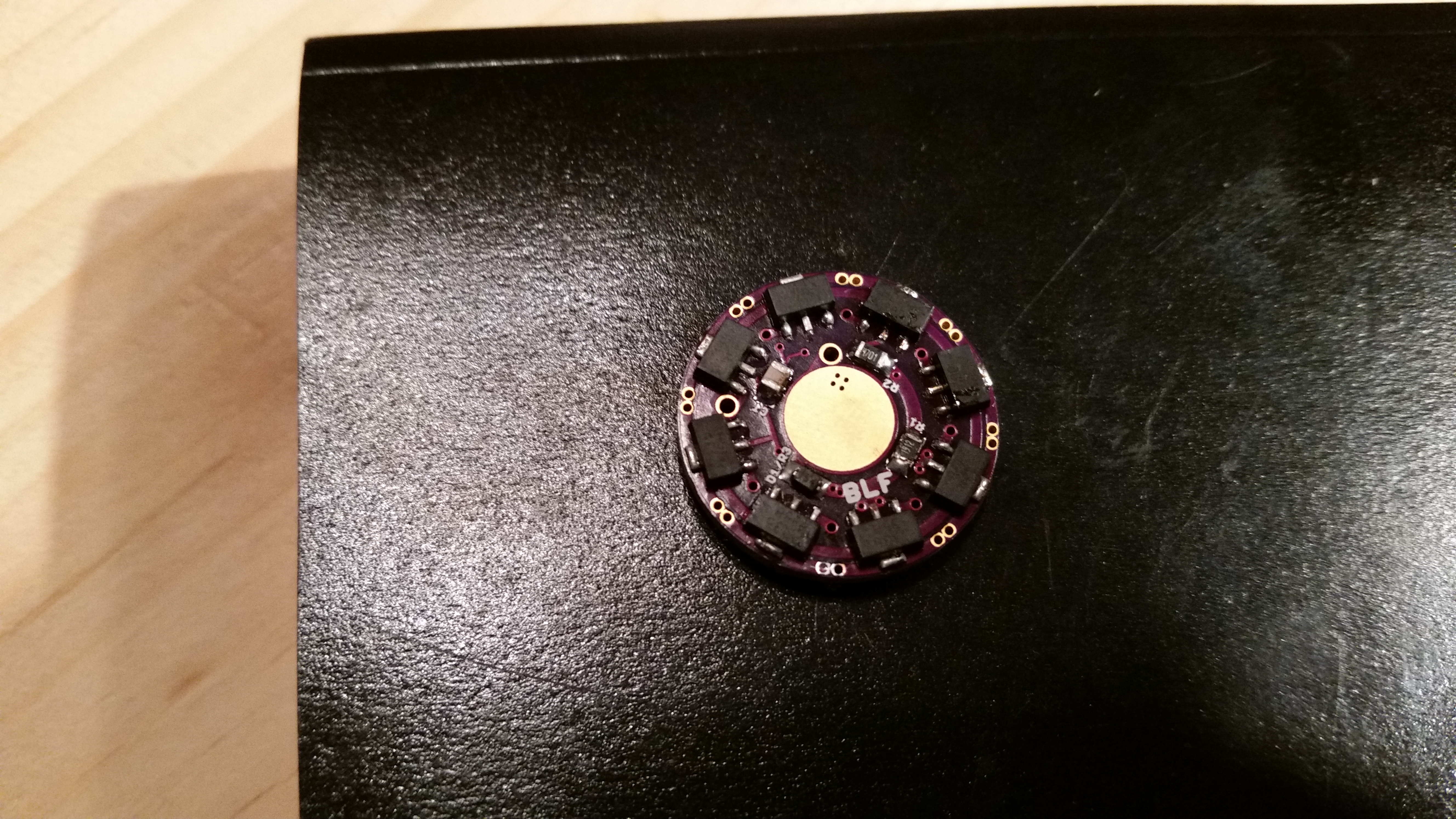
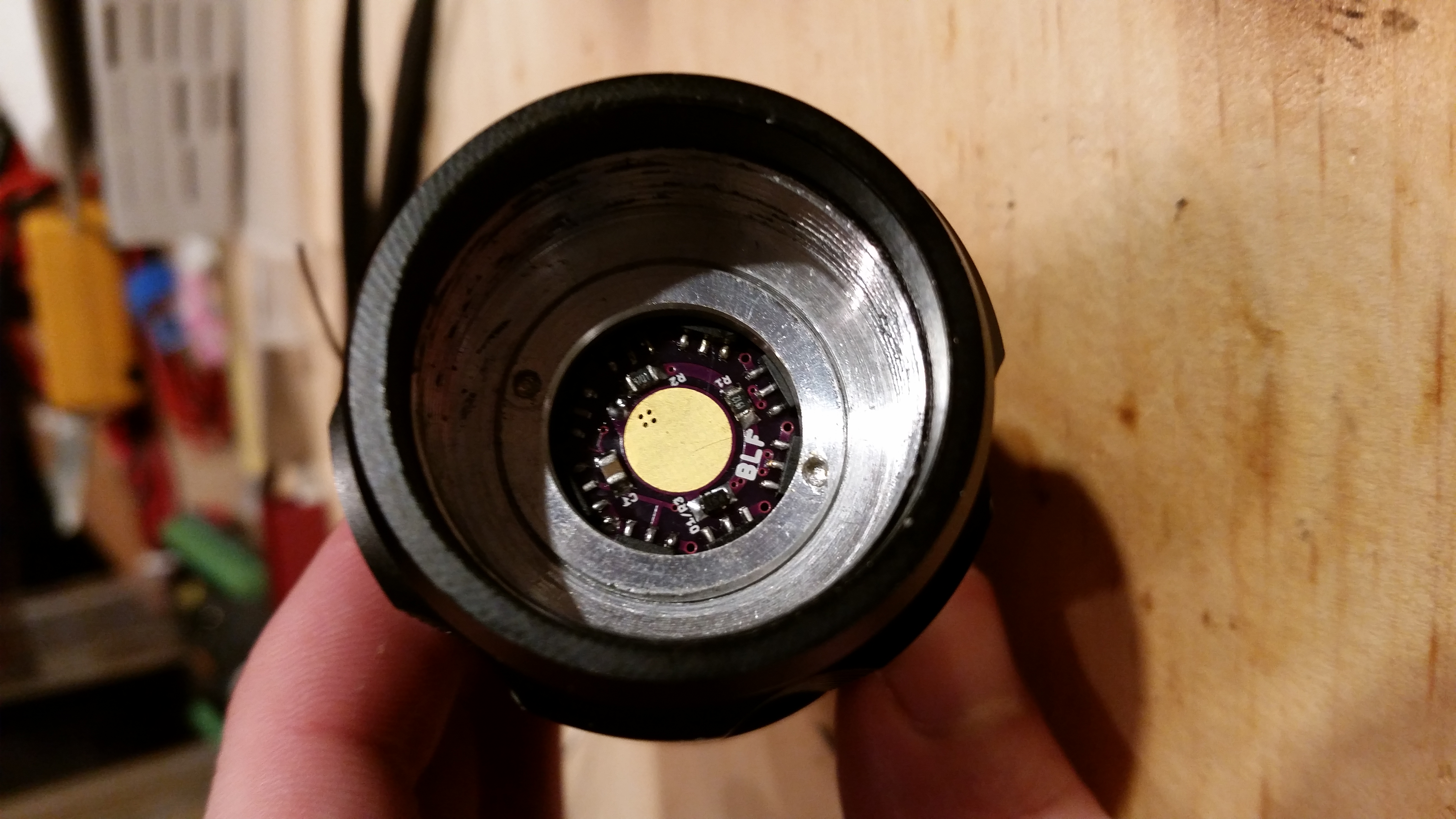
I have installed & tested this driver in a Gearbest Ultrafire F13. I populated it with 12x7135, 8 on the bottom and 4 on the top. I made sure to populate the space right next to the offtime cap so that we could see how tricky that got. As I mentioned earlier, the spacing of the 7135’s on top is such that the tabs miss the shelf, allowing the driver PCB to fully seat against the shelf.
I think that I intended for the LED+ / LED- vias to take 20AWG but they do not. 24AWG fits with room to spare. I may release a revision to address this, but there’s very little space left! Probably better to file down 20AWG if you want it to fit.
Sorry for the cellphone pics.
Now that I have built v015, I feel confident that the board is ready for prime time. I have revised the silkscreen for C1 and released v016. There are no functional changes from v015.
I made a mistake with the firmware. I started with STAR_off_time_1.3.c. I disabled moon mode through the define (commented it out). I also reversed the if/then terms for Star 3 since I don’t solder stars and wanted H-L. Apparently I did something wrong because I ended up with L-H. Come to think of it I still don’t see my mistake. Oh well, I’ll take a closer look later. Maybe I shorted the pin on the MCU.
Thanks for the complements on the build. It needs a tall battery spring, I started with a Nanjg 105c spring and it was way too short. I switched to the D-type spring (5/8/8/0.8mm) from IOS and it was barely enough. I’ll have to install a tall post I think.
Somehow I lost track of it in the process, just stumbled over it through the oshpark thread.
This is like a one-that-fits-all driver, including the BLF add-ons off-time memory and zener mod.
Thanks for that one.
Errr… would you mind sharing the brd-file if you happen to have one?
I need that driver slightly larger (24mm) and would adapt it. But I have no software to alter the gerber files, just Eagle here.
Tbh, I’m thinkin’ of some other minor tweak 0:) (12x 7135 suits me well, that might give room for a larger spring base to fit IOS type A, B and D)