But if it's that sensitive to the trace length, the number you read from measuring the temporary pot won't be the same as what it would need once it's replaced with a fixed resistor. :~
Maybe so, maybe not. It’s a place to start. That or random value resistors from the bin until one works. Not sure if trace length of highly conductive copper acts the same as highly resistive pot wire.
RBD, comfy was probably pointing out that if you use a pot you’re using hookup wire of some kind to tie it into the circuit in place of a 0805 or 0603 resistor. All that hookup wire could have an effect on inductance, capacitance, and/or resistance…
I was thinking of one of those smallish smd types they use on the charge boards but he’s certainly got a point. I just figure you’ve got to start somewhere. Maybe test it first on an SRK DD where the traces are longer and more similar to the wire length and the board is easier to work on.
This most likely won’t become a shared project, it’s to specific / not enough demand and right now it needs a few tweaks, I got it working but it’s no where near “ready to go” so really I’m just showing off.
This is a set of S->P carrier conversion plates for an olight SR51 WarHawk made for me, he made them perfectly to my spec’s but unfortunately my measurements were a little off on the post hole alignment.
It works well enough for me by if I ever do someone else SR51 I’ll need Brian to make a couple tweaks, I’ll also use soldered in place brass rods instead of the stock aluminum rods.
Note in stock setup the rods don’t carry any current. The top post is +, two outter ones are ground. Running a 17dd driver in my SR51


Design process


AOD510 works beautifully on the SRK-DD with no resistors whatsoever, so unfortunately that's not gonna tell you much.
The way I came up with the 70N02/17DD's 130R resistor was by just trying the common values from 10 ohms up to 200 ohms.
I’d say it tells us plenty! I don’t think you mentioned before that AOD510 worked in the SRK-DD. To me that definitely makes it sound like more of the same problem, which is encouraging.
This is the sort of thing I was thinking of in post #966, although as I said I have little knowledge of the subject:
http://jeelabs.org/2012/12/05/ringing-mosfets/
I’d say this sounds similar to our problem. A larger resistor may be in order. At some point a small gate driver may be a better solution.
Yeah, it's useful info about the problem in general but not for finding a resistor value that'll make it work on the 17DD.

Looks cool, but I don’t understand your comment about the posts not carrying current? Nevermind, I get it now. The black rods are aluminum, and with your mod they carry BAT- back up to the top plate. Got it.
From your testing with the Vishay 70N02, what happens when the resistor value is too high?
The gate resistor raises the minimum PWM level where it will first light the LEDs. The amount of light is the same (say, 100R min PWM is 3, 200R min PWM to get any light is 5 or 6). On the SRK-DD, with no gate resistor, it'll make light with the PWM all the way down at 1. Not good... as shown in your link, the FET takes longer to turn on (and off). If it's necessary then it's necessary, but I'd much prefer to find a way to do it without the resistors. This combo of parts doesn't require resistors, as shown with the SRK-DD and even the half-ass version of sticking the FET onto a Nanjg 105C board. It's not the parts, it's something weird going on with the 17DD's PCB. I don't know if it's trace length or something like the FET being jammed right up against the attiny.
What I did on the SRK-DD with the inductor inline with LED+ to further drop the low mode down to sub-lumen level is different since it's on the output side, and doesn't affect the switching speed of the FET.
I've even thought about trying it with two 17DD boards - one hosting only the Nanjg parts, and another hosting only the FET. But then, the necessary wire between the two boards from pin 6 to gate would be a significant factor and wouldn't really rule out one thing or the other. If it worked using two boards and no resistors, it could be either because of the separation between FET/MCU or from the added length of the connection to the gate. A test that gives ambiguous results is probably not a very good test.
I’ve been reading this application report from TI: http://www.ti.com/lit/an/slpa010/slpa010.pdf
It’s really informative on the subject. Of course the ringing occurs due to the rapid change in voltage or current on the power side of the FET, and then through some method or another ends up on the gate pin too. While their focus is on voltage margin for the FET parts (we aren’t close to the voltage limits of course) they do clearly illustrate that just a short trace length makes a big difference in ringing. They are showing it because we’d need to know that for using a scope to diagnose what’s happening at the FET.
I’m going to say that I think the SRK-DD board is probably doing the same thing as the resistor in the BLF17DD - softening up the turn-on/off. We take the same efficiency/losses hit and heat bump in that case.
We have no caps for the FET. The app notes are about tuning up synchronous buck converters, but it seems like some capacitance might help us here too. Of course capacitors are expensive and take up a lot of space.
I’ve read a good chunk of the document at this point. Granted that it does not directly apply to what we are doing, but it seems pretty cut and dry here: either get some capacitance very close to the FET or slow down the switching time.
EDIT: I don’t know which capacitance numbers mean what (input / output / reverse transfer) but the datasheets show significantly less capacitance for the AOD510, especially for Ciss and Crss. Maybe a simple 1uF input capacitor located very close to the FET would knock the problem out.
Talking about a 17mm DD family.....
As an end user of driver boards without experience on designing board lay-outs or the ability or will to program MCU's, but with a lot of enthousiasm for using the DD-boards....
for the small light mods I usually do, it would be really nice to have a 17mm (and 15mm) DD board with no components on the battery side (even not a few tiny resistors), and using (apart from the FET) only components scavengable from other boards like the 105C.
Here in Europe every Digikey or Mouser order comes with $25 shipping costs. I can ask Richard for a special delivery of components because he is a really nice guy but he normally does not ship outside the US (he did get me a batch of those Vishay FET's :-) ). The way I will mostly likely build up these drivers is scavenge a qlite, it has the modes I am happy with.
Not sure if it is possible to make a design like that....
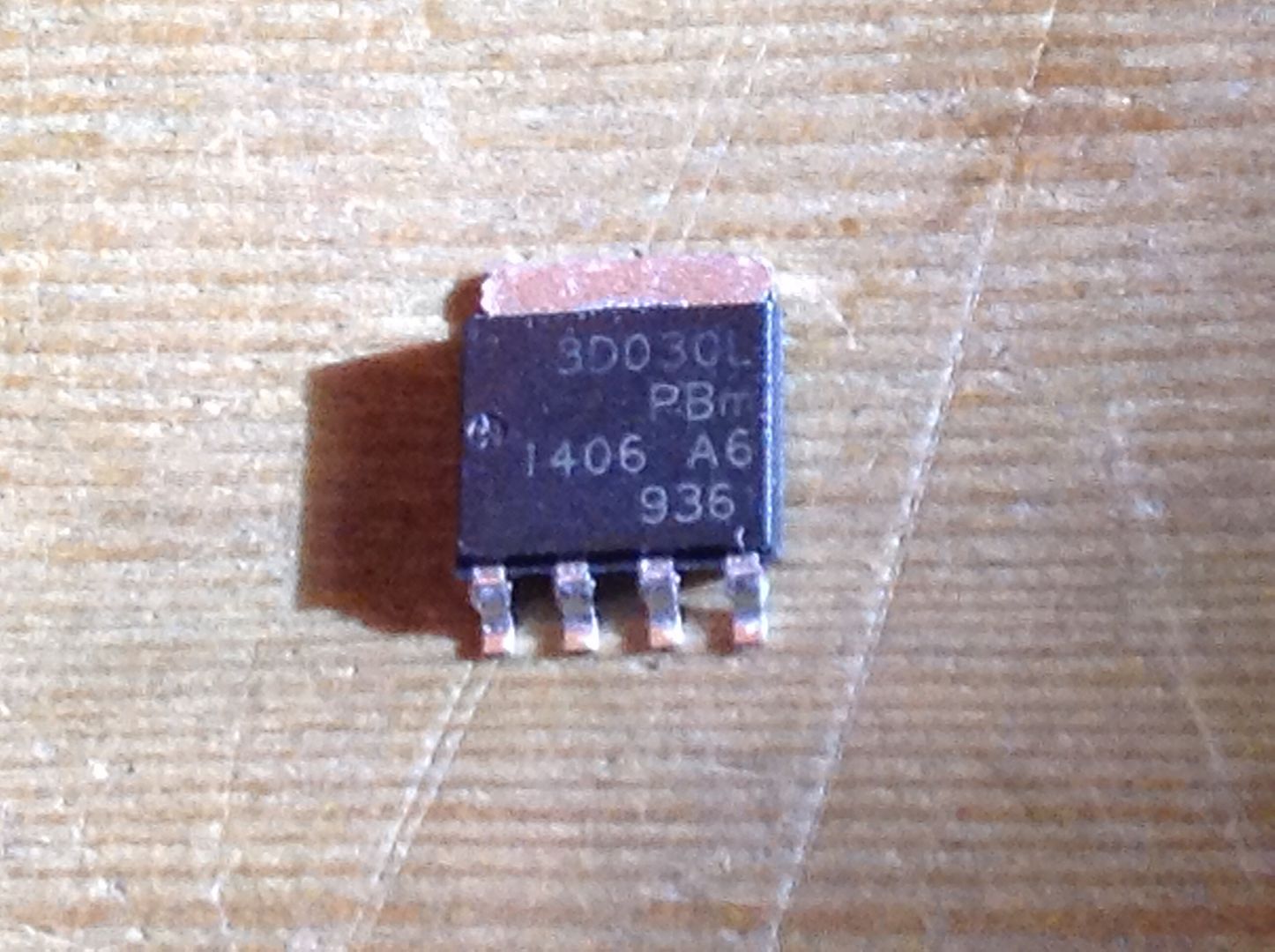
I think it’s certainly likely if the lfpak56 gets a board designed around it. The only real difference is the added gate resistor. I like the singe sided idea myself with only spring and stars on the back. I think there’s room for the Zener as well but I’ll have to wait on either learning eagle or more interest in that FET. It does seem to be on ebay(UK).
My sentiments almost exactly. I am willing to sacrifice some beauty for functionality. We are the only ones that will look at the positive terminal and see the presence or absence of chips and have an opinion. I suppose it is analogous to a woman in pretty matching underclothes- perhaps no one will see them but she knows that they are there and it makes her feel happy.
I would like to take this opportunity to thank you guys again for all the work you are doing for these projects. I only understand a fraction of what you say but I enjoy the progress you have all made and shared with all of us. Thanks.
My latest driver project can be used that way. With just an FET you can ignore all the warnings about needing a custom firmware… just pay attention to the warnings about how hard to build it will be. As I say in the thread, it should not be quite as difficult as it looks - but it’s close. It does use all 0805 sized components, so you can use what you rob from the Nanjg 105c, but since I bypass the protection diode you’ll want to use a different value for R1. Pads are available for either DPAK or LFPAK56 MOSFETs. 17mm DD+7135 — linear regulated driver w/ FET turbo As you can see, there are nothing but 7135’s on the bottom. The entire bottom of that board could just be deleted and replaced with one big BAT+ pad.
For the extra 0805 components (R1, gate resistor, gate pulldown resistor) you can just get them from Chinese eBay vendors 100x for a buck or whatever.
Which LFPAK56 FET are you using?
What's the minimum-cost oscilloscope that'll give us a picture of what's going on with the gate signal? Are the sound card-based DIY things good enough? Are the Hantek 2-channel USB scopes worth the going price of $60-70? We don't need lab-grade precision, just something that shows the waveform, right?
In a like-for-like comparison between the AOD510 & 70N02 - identical SRK-DD drivers/firmware, same cells, same 3XP/XPG2 board, I measure 41.5mV drop across the AOD510, and only 32.6mV across the 70N02. So the specs in the datasheets that show the 510 having lower Rds(on) don't hold true in this lower-voltage application.