The spike is most likely coming from the inductive kickback voltage from the emitter wires. When the FET switches the magnetic field in the wires collapses and generates a voltage spike. A cap across the protection diode is not a good way to stop it. Try a diode across the emitter wires at the driver (bar side to LED+, triangle side to LED-). The diode should have a decent current rating.
1A schottky diode (IN5817) between LED+ and LED- had no effect at all. On a driver with the gate resistor replaced with a jumper, the scope shows no change and the driver doesn't change modes reliably.
I just built a few 17mmblf drivers with rmm kit, does this voltage spike have an effect on those? I haven’t used them in any lights yet.
If it's one of the versions using the gate resistor and it changes modes correctly you can use them as-is.
-----
17DD with the extra cap & resistors eliminated:

Oh, and the AOD510 that didn't work before works properly now in the extra cap/no resistor setup. That's why I added it to the Digikey shared carts.
I'm sure there's history on this, but does the AOD510 MOSFET perform as well as the Vishay 70N02?
We might need to get some current numbers to find out for sure but it may do even better. On state resistance is hard to compare between fets since they are often spec’d at different gate voltages and aren’t exactly the same from one FET to the next.
I don't have a current measurement, but I have checked voltage drop across both in a like-for-like setup. 70N02 = 32.6mV, AOD510 = 41.5mV. Higher voltage drop means higher resistance. So they're not equal, but the AOD510 is readily available and relatively affordable and they're only 'not as good' when compared to a really excellent one.
And you can buy it ![]() (that’s always a plus!)
(that’s always a plus!)
Comfy what are you using for the + button on that driver there? Very clean install (as usual). Also very good news about the 510’s! I was really getting worried as I’d been testing different gate resistor values (I have every resistor pack coming from fasttech so I wasn’t gonna give up yet but I tested every value resistor I had in the spare resistor tube and nothing had worked yet so that’s great to see). Thank you for your time/money.
Side note my 858D will be here Tuesday!
Just a piece of scrap sheet copper, I think it's around .040" thick. Not much room in that little Z1...
Revision revised again (probably won't be the last time, either)!
dave_ suggested an alternate fix in the 'scope images' thread (post #50, in case the pagenumber thing breaks the link for you). Instead of adding a second capacitor in parallel with the diode (which does work acceptably well), just relocate the one original cap from its original spot between the diode output and ground, to just plain between B+ and ground.
This is the extra-cap version:

Gives waveforms that look like this:


Acceptable, and it makes the driver reliable with the gate resistor deleted. But requires an extra capacitor.
dave_'s suggestion:

Gives you this:


Waveforms look better, needs fewer parts, and works just as well.
The capacitor can go anywhere on the board where it can connect between B+ and ground. There are many options on top or bottom of the board that will give the same connections. On the topside, there's a single ground via right beside the four B+ vias at the LED+ wire pad, if you'd prefer that it not be on the spring side of the board.
A larger value capacitor will flatten the oscillation more than shown above, but this works well enough and the part is the same as what comes on the Nanjg boards, for those who are using that as a source instead of buying bare parts in bulk. For those wanting to get more involved, you can change to a larger value cap if you wish. Experimentation required, and probably needs to be verified with your own scope images if you want to try something different.
ANOTHER SET of shared carts - same components as before, just with 1 cap per driver instead of 2:
shared cart- BLF-SRKDD | Digi-Key
I hope you dont mind me posting this here but I got my first Osh Park shipment today. I just need to know now how it all goes together. 
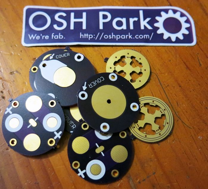
Uh-oh! Those spacer boards seem to be missing the center hole?!?
Is there a way to order different boards with the same order? I just ordered some things and I had to pay two times…I hope they will send it together.
+1, had to do that myself and the two sets were fabbed a week apart and shipped separately. They might do overseas differently as Steve just posted an order with several boards that came together.
I did three orders right after each other, three separate pay sessions, but they arrived in the same envelope. Apparently the Oshpark software has an efficiency thingy build in, or even perhaps there are real humans involved there somewhere :-)
I thought I did something wrong, I would definitely feel bad if they would send a 1$ order separately.
I used the little FET Scott sent me with the then new BLFTiny10 and put it in my Texas Poker, running a bit over 3A from an Efest IMR10440 to a de-domed XP-G2 R5 1A. None of the extra resistors or such was known at the time. I don’t have moon engaged, just running 4 modes. And it works fine. So far. I use it pretty often and in various modes, but usually set it to come on in the lowest mode before shutting it down. After I built it, the issues came into light of the possible mode changing failures. I had considered opening it back up to engage moon mode, but feared it would bring this issue to my driver.
Should I worry about an issue arising? This is an expensive light, one of a kind, and I don’t relish making changes unnecessarily. If something get’s damaged it might not be possible to replace or at the very least will be expensive to do so. With it in working order, should I worry about it?
Pretty sure I’d never go this route again, having the full custom Ti light made turned into quite a more costly venture than expected. With the cost of an Olight SR90 AND Fenix TK61 combined rolled into this 3” Ti light, I’m not eager to make changes to it that don’t need to be made, ya know? I’ve already been into it 4 times with driver changes and one emitter change. As most of y’all know, the more you work on one the easier it is to kill reliability. I initially had requested a second pill, forseeing this potential even a year ago. But, alas, I only have the working light with no spares.