Driver Info: HX-1175b & HX-1175B1 (Pic Heavy)

The scope should have a test point you can use which produces a 1khz square wave or something (marked on the front). Use that to get started. I know almost nothing about scopes and can hardly use my own surplus scope.

The buck controller senses current [by measuring voltage drop over the sense resistor bank] and turns the FET on and off accordingly (and rapidly). At high input voltages the FET will be off a lot of the time (think 50% if input is double output). This is exactly what we want for regulation; other parts of the buck circuit ensure that voltage never goes too high - we don’t need to talk about how but it’s related to the rapid switching of the FET. A PWM input will tell the buck controller to keep the FET off even more in order to give lower-than-maximum modes. Keeping the FET at 100% duty cycle (always on) is direct drive. If it’s not turning on and off rapidly then maximum voltage will be allowed on the output. In a buck circuit the FET should never be at 100% duty cycle. [100% duty cycle is fine on the PWM input of the buck controller though, since this just tells it “don’t turn off any more than you normally would to maintain the current you are supposed to”]

The point of the above is to explain that the buck controller itself is in charge of regulation. If you bypass it that is bad.

I also have no formal electronics training, so you can only wave that flag at me so much ;-). I’m still happy to help.

Let’s get down to business:

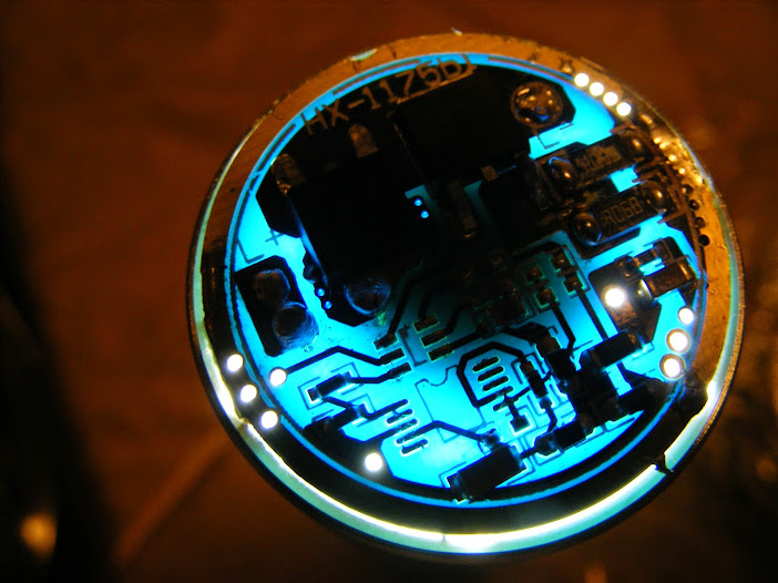
  • You never posted a clear pic of what’s under the MCU (traces). That might be helpful or it might not.
  • In post #29 you say ‘clockwise’, but we mean counter-clockwise, correct? (If not post a drawing to help please.)
  • In post #29 what mode is the driver set to?
  • Let’s re-check pad voltages without the MCU installed. Please record them so that we may compare with your results from post #29. This is what I really feel like we need to see right now.
  • If you haven’t gotten a handle on your scope yet, maybe try this: If you have a working stock driver hooked up, please power it up and set it to medium. Do a quick check with your DMM and look for any pins which seem to have a significantly different voltage from the values recorded in post #29. [If the driver was set to medium for your results in post #29 then recheck with the driver set to High this time and look for pins that show a different voltage.]

FYI: In my last suggestion we are not looking for a true/accurate voltage. The DMM will probably show something inaccurate, but hopefully different, for different PWM duty cycles.

OK, looks like we are in business for good this time.

Sorry for the delay. Finally got a chance to get a MCU and buck controller trace shot. Wight, I will have to get back to you on clockwise/counter later. I'm too tired to think straight right now. Actually, the trace picture below should answer what you are seeking. Full power is going to the bottom left Pin in the below pic. The Pin above it is the Ground. The second Pin up on the right side of the MCU appears that it could be for voltage dividing.

As discussed earlier in the thread. PWM is coming out of the top left MCU pin in the above photo. The trace show it going into resister to ground and through another resistor to the bottom left Buck Controller pin. Duty cycle readings with a DMM confirmed the PWM signal at both points.

In the past, I tried to get the driver to turn on feeding power to the top left MCU pad, but nothing happened. I would like to try that again as I wonder if I did something wrong. It seems like it should work.

Anyway, relocated the PWM feed to the lower left Buck Controller pin and am now getting normal current readings at the emitter. With stock resistors current read:

PWM Current

1 Too low to realy measure. Says .01 amps sometimes

3 Same as above

9 Very low. less then .06 most of the time

27 About .28 amps

100 1.9. ish amps

255 Almost 7 amps

Added one R10 and got the following readings:

PWM Current

1 Too low to realy measure. Says .01 amps sometimes

3 Same as above

9 Very low. less then .05

27 About .3 amps

100 2.3 ish amps

255 Starts around 9.7 and drops fast and stabilizes just above 9 amps

Here are a couple pics of the set up.

Check out the size of those stock resistors. That green resistor I added is a 1206 size. For other pictures that may help more clearly see the connection points, see Post 39. Just keep in mind that the wrong pin on the Buck Converter is used in that post.

I only ran the driver for about a minute or so. Since I don't have the beefy brass ring to absorb heat, I didn't want to run too long. Driver was warm to almost hot. Heat seemed to be from the voltage sense resistors and the Large Diode/FET side of the driver. My impression is that the driver will run fine at this current if properly connected to the pill for heat sinking. The large diode is rated for 10 amps per the data sheet.

Something was whining pretty loud at PWM 100. Mounting in a light might mute most or all of it. I'm not really concerned about it. If anyone wants me to try anything to get rid of it, let me know. I can't guarantee I will get a chance to try it, but will if I do.

Here's another trace shot. It's hard to get the traces that are over the cell side positive terminal.

Just wanted to say a big thank you to BLF member wight for taking the time to help me develop a MCU mod for this driver. His (assuming he's a he) guidance not only helped me figure out this mod, but he also noticed a mistake that I made at an earlier time when I swapped out what I thought was 2 FETs, but were actually a FET and a diode. The mistake didn't seem to hurt the MT-G2 and it made the driver run cooler, but it would have most likely been problematic to less hardy diodes like XM-L's.

Thank you wight

Here's at attempt at a consolidate the "Attiny13A piggyback how to" so the whole thread doesn't have to be read. Legend:

A - Pull the HX-1175's MCU

B - Connect PWM feed from the Attiny13A to this pin on the Buck Converter (ignore the red wire. That is not the correct pin).

C - Connect ground for Attiny13A any where around the ground ring

D - Connect power feed to Attiny13A here

I’m glad this thing is working. Now to find a reliable source for these.

And one with an un-sanded buck controller.

I’d still like to see a picture with all pin descriptions. I can’t understand when you do lists or clockwise / counterclockwise.

I consider the source I listed in the OP reliable.

The paragraph above the first picture in Post 50 doesn't have the info you need?

How does this driver behaves on different voltages?
It’s listed as 3-18V but I guess it is buck only like always…

I think I’m starting to see. You say “Full power is going to the bottom left Pin in the below pic.” I read that as “the bottom left pin” - a pin which does not have anything hooked up to it. That’s why I assumed you meant the bottom right. Now I see you meant the pin above the bottom left pin. When you said “full power” I was also confused since I wasn’t sure what you meant by that. Looking back at post #29 I’m sure you meant ~4-5v, not battery voltage. (remember, as far as I know this is a mystery MCU. So I don’t rule out putting battery voltage on it). Anyway I think I’m clear now, thanks.

There are 5 pins hooked up though, so I’m still curious what that final connection is on the bottom right. Looks like it’s not hooked up to anything but a bunch of unpopulated stuff. I still wonder what it was for…

Werner:

I have only been using the driver with MT-G2 using 2S and 3S cells. Based on the way it behaves, I think it will have no problem with 4S cells. I will try soon to find out. I will also try 1S cell with an XML.

wight:

You're absolutely right on all counts. So sorry for the confusion. The second Pin/Pad from the bottom on the left is receiving a little over 3 volts. I'm not sure why the there is a difference between what I measure now at that Pad (without the MCU in place) and what I measured then with the MCU in place.

I will be modding another driver soon. I will take voltage readings again both with the MCU on and off the board and report back more clearly.

WOW
Nice job!!!

I wish I had time trying to replace the MCU on LD-29 :frowning:

I think Werner is wishing it was a Boost/Buck driver (or maybe it is? - unlikely :frowning: ).

It’s partly just the way I read things. One possible reason for the different voltages you observed would be “potential”. If you did not use the same ground point with your DMM you could get different readings. I look forward to your measurements with the next one. That should be telling!

Maybe I’ll at least probe one very soon.

Finally got my two HX-1175B today.

One with 2 x R068. About 6,8A on high

One with 2x R062. About 7,8A on high.

Modded one that had 2xR068 stock. With similar (combined) values as my other one, output was a bit different. So, maybe its wise for people do test these things on their own drivers.

ImA4wheelr, the way you connected it in post 52. Does it whine in any of the modes that way too? What PWM frequency are you using?

Anyone who is able to incorporate low voltage warning and cut off for 2 cells in series?

Glad to hear you got the right driver finely. Did you get the "B1" version?

I'm assuming you are meaning using a 105C driver board as opposed to just an unmounted Attiny chip. The PWM feed should only be wired one way as the first way I did it basically takes you into direct drive. I didn't notice any whining, but I have to tell you that I'm pretty deaf to high frequencies.

I think the whining was amplified by having the driver hanging in the air and not having the heavy brass ring on the driver (like I did with the Post 52 pictures). I think just mounting the MCU properly and also mounting the driver in a light would eliminate most of the whining. I bet my potting recipe would absorb the rest of whining as it is a clay like substance.

I want to solve the whining issue too. Hope to get back to the driver this week. I need it for a couple lights. I'll ask my wife to listen and report back.

EDIT: Opps, forgot about your frequency question. 9kHz. Here are the lines from DrJones' MiniMo FW:

#define F_CPU 4800000                    //use fuses  low:0x75  high:0xff
 TCCR0A=0b00100001; TCCR0B=0b00000001;  //PWM setup, 9kHz

Hooked PWM to the 30,000 ohm resistor on the MCU side of the resistor, got ground from the ground ring and power in to the ATiny13A from the pad at the lower right side of the board.

Once I figured out the wiring to the e-switches in the TK61 (&@#~!!) it pulls 7.15A to the de-domed XM-L2.

Have the 10-pin and 6-pin chips been definitively ID'd? The 10-pin one looks awfully similar to the Linear Tech buck or boost controllers.

That would be cool if someone knew the answer to CC's question.

DBCstm wrote:

Hooked PWM to the 30,000 ohm resistor on the MCU side of the resistor, . . .

For some reason, I couldn't get the driver to work when I tied in down stream from the point I tied into in Post 52. I was tying VCC in at a different point though when I did that. I will have to try that again. Do you know if there is any benefit to feeding the PWM through the resistor? Where I tied, PWM of 1 works. How low can you go tying in through the resistor?

Tried the recipe in post 52 with a regular Qlite just to test.

Nothing. Cant post picture to photobucket right now due to maintenance or something.

Any reason why a regular Qlite should not work?

Are you tying in where the "B" is in the picture or where the wire is soldered. The wire is wrong.

DBCstm tied in on the MCU side of the 30K resistor. That might work.

EDIT: A picture might help if the above doesn't fix you up.

Not sure exactly what you mean.

I tried on the MCU side of the 30K resistor too.

Here is how I wired it first.

From the Qlite, the wires were connected here: (picture from my other HX1175B, looks extra dirty due to light)

Found my error when looking over this post. You can see it in the first picture. Two of the legs where the HX-1175B MCU stood were connected. Problem solved.

There is some high frequent whine on "medium" with the qlite too. Mode spacing with regular Qlite firmware is really strange.

Low - 0,4A

Medium - 0,87A

High - 7,9A

Im glad it works. Thanks a lot ImA4Wheelr! :)

When I learn to program and flash these drivers I should be able to get nice mode spacing.. Please let me know if someone is able to find a solution for the whining.

Here is a close up picture if you need it.

Edit after a little tweak:

0,05A

0,99A

8,12

Well regulated down to about 5,6V. High sinks down towards 8A.

AFAIK they have definitely not been ID’d. The 10-pin is almost certainly an MCU of some type though…

RaceR86’s “other” board shows an “A” on the 6-pin chip. The 10-pin MCU is really well ground, looks like they built a machine to do that.

Racer86’s 10-pin chip does show an important marking though. There’s the dimple for pin-1 but there’s also a little dot beside that. It seems that the dot must be part of the manufacturer’s marking or logo, it almost certainly does not indicate a pin or anything. I don’t know who. Maybe someone wants to pour over sites like this one.

Where is the whining coming from, can you tell? Consider potting the driver, as suggested by ImA4Wheelr. I assume that epoxy potting will be much better at quieting it down than his clay-like recipe, but also way less reversible ;-).