Just a piece of scrap sheet copper, I think it's around .040" thick. Not much room in that little Z1...
Revision revised again (probably won't be the last time, either)!
dave_ suggested an alternate fix in the 'scope images' thread (post #50, in case the pagenumber thing breaks the link for you). Instead of adding a second capacitor in parallel with the diode (which does work acceptably well), just relocate the one original cap from its original spot between the diode output and ground, to just plain between B+ and ground.
This is the extra-cap version:

Gives waveforms that look like this:


Acceptable, and it makes the driver reliable with the gate resistor deleted. But requires an extra capacitor.
dave_'s suggestion:

Gives you this:


Waveforms look better, needs fewer parts, and works just as well.
The capacitor can go anywhere on the board where it can connect between B+ and ground. There are many options on top or bottom of the board that will give the same connections. On the topside, there's a single ground via right beside the four B+ vias at the LED+ wire pad, if you'd prefer that it not be on the spring side of the board.
A larger value capacitor will flatten the oscillation more than shown above, but this works well enough and the part is the same as what comes on the Nanjg boards, for those who are using that as a source instead of buying bare parts in bulk. For those wanting to get more involved, you can change to a larger value cap if you wish. Experimentation required, and probably needs to be verified with your own scope images if you want to try something different.
ANOTHER SET of shared carts - same components as before, just with 1 cap per driver instead of 2:
shared cart- BLF-SRKDD | Digi-Key
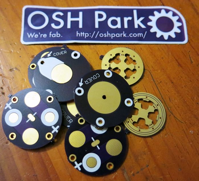
I hope you dont mind me posting this here but I got my first Osh Park shipment today. I just need to know now how it all goes together. 
Uh-oh! Those spacer boards seem to be missing the center hole?!?
Is there a way to order different boards with the same order? I just ordered some things and I had to pay two times…I hope they will send it together.
+1, had to do that myself and the two sets were fabbed a week apart and shipped separately. They might do overseas differently as Steve just posted an order with several boards that came together.
I did three orders right after each other, three separate pay sessions, but they arrived in the same envelope. Apparently the Oshpark software has an efficiency thingy build in, or even perhaps there are real humans involved there somewhere :-)
I thought I did something wrong, I would definitely feel bad if they would send a 1$ order separately.
I used the little FET Scott sent me with the then new BLFTiny10 and put it in my Texas Poker, running a bit over 3A from an Efest IMR10440 to a de-domed XP-G2 R5 1A. None of the extra resistors or such was known at the time. I don’t have moon engaged, just running 4 modes. And it works fine. So far. I use it pretty often and in various modes, but usually set it to come on in the lowest mode before shutting it down. After I built it, the issues came into light of the possible mode changing failures. I had considered opening it back up to engage moon mode, but feared it would bring this issue to my driver.
Should I worry about an issue arising? This is an expensive light, one of a kind, and I don’t relish making changes unnecessarily. If something get’s damaged it might not be possible to replace or at the very least will be expensive to do so. With it in working order, should I worry about it?
Pretty sure I’d never go this route again, having the full custom Ti light made turned into quite a more costly venture than expected. With the cost of an Olight SR90 AND Fenix TK61 combined rolled into this 3” Ti light, I’m not eager to make changes to it that don’t need to be made, ya know? I’ve already been into it 4 times with driver changes and one emitter change. As most of y’all know, the more you work on one the easier it is to kill reliability. I initially had requested a second pill, forseeing this potential even a year ago. But, alas, I only have the working light with no spares.
Agreed if OSHPark had an “add to cart” deal and you could order multiple boards that would be excellent for sure
Remember its a tiny company. I think it has to do with how they process them once the panels come back from fab, I imagine it can be pretty confusing breaking all the boards apart and packaging them up so if they’ve got a system that works I dont think they need to change it.
I’ve personally placed over 3 dozen orders for over 120 boards and never once had an issue, they’ve got their system down pretty well, other than the strange way you check out for each set of boards at a time it’s a pretty hassle free system they’re running. I’ve said this before but cudos to Lean and the rest of the OSHPark team, they enable so much of what we do here, this flashlight hobby of ours would be a lot more expensive if it wernt for them.
I think it's almost certain that any board that has re-used the Nanjg's original diode/capacitor layout in the power supply to the MCU suffers from the same overvoltage thing shown in my scope images. Even an original 105C does it, though when driving 7135s it doesn't rise to the level that causes odd behavior.
Move the capacitor at C1. Originally it goes between the diode's output and ground. The boosting goes away if it's moved to between B+ and ground, and then gate/pulldown resistors are no longer needed. In existing designs replace the gate resistor with a jumper. In new designs their pads can be eliminated entirely, freeing up valuable space.
Is there a guide anywhere for designing these things? Is there anything that will let you edit the design files from Oshpark?
Design? No. Layout? Yes. Matthaus posted a thread on layout using Eagle. Learning Eagle is definitely a both-feet-first endeavor.
Editing what’s on Oshpark? Mostly no. Many/most people upload only “gerber” format output files to Oshpark. In an EDA suite such as Eagle you work with it’s native format and then output gerbers as the finished, mostly uneditable product. Think of it as writing a document in MS Word and then printing it to an Adobe Acrobat file. Very similar end result here - while you can mess around with a Gerber, it’s about as effective as trying to make changes to a complex document that’s already been committed to a PDF.
Mattaus and WarHawk-AVG both have the BLF20DD Eagle files IIRC. I believe it was Mattaus’s intention to keep the circulation of the Eagle BRD/SCH files down in order to prevent a flood of minor variants confusing people (or worse, a flood of non-functional variants confusing people). I’m sure one of them can hook you up!
I've been out of the loop but if anyone wants changes made just let me know. The only thing I ask is that we keep the changes to single revisions and preferably single versions of a particular size. I don't want to have to manage 5 (bum plucked number) different versions of the 17DD just so that we can have one with a resistor, one without, one with a slightly different layout, one with extra caps, one with a FET, one with AMC chips, and so on.
I'm pretty bad at revision management as it is, going crazy is a recipe for disaster. The ultimate goal here is ONE perfect DD board.
I’m up for it Mattaus if you want to send me the brd and sch files….I can tweak what you have and then send em back to you to post to OSHPark…this way the revision stays sane
In reference to MRsDNF’s post #1046 - I made an error on my layout for the v13 contact-ring/adapter boards. I knew better, so it was just an oversight on my part. I will post a new version very soon, but not tonight.
Dan @ OSHPark had this to say on shipping:
Credit goes to WarHawk for fixing the boards up. I've removed the old 17/20DD boards and repalced them (and added a 22) with VERSION 1.0 of them. I've started fresh because the revision numbers were going all over the place. I'll need a BOM provided for these as well. I will then add them to the description.
https://oshpark.com/shared_projects/IHvO85FY
https://oshpark.com/shared_projects/SNtRM4Vs
https://oshpark.com/shared_projects/D2dJbbBm
Cheers,
- Matt
Nice Matt! Like'n the rev # - hopefully easier all around to track. Thanks Warhawk and of course, comfy! comfy has been amaz'n on this mod, plus I really like we now have other FET options.
I’m not going to keep beating on it, but as I said in comfychair’s thread I do not think that this is the ideal layout. My understanding is that C1 should be as close to MCU pin 8 as possible for best decoupling. Since we are putting C1 before D1, that means that by proxy D1 should also be as close as possible (to allow C1 to get closer).
comfychair clearly demonstrated that the board works as laid out now in the new v1’s, but that doesn’t mean that we won’t run into a scenario later where it’s a problem.
D1 is pretty dang close to pin 8, isn't it? It's closer than in the revision using gate resistors, the diode no longer has to move aside for the gate in/out vias. C1 physical location no longer matters as it's no longer filtering pin 8 directly (there's now a diode in the way), it's filtering battery voltage instead, which is where the big spike used to be.
The old boards with longer traces and jumpers all over work fine with the cap relocated, I am having a hard time imagining a scenario that would bring about anything like the issues you got with the old circuit.