Would the BLF Tiny10 give you a solid platform to piggyback the ATtiny and supporting hardware and be able to shoe horn it in the pill?
comfychair and others seem to be getting VERY good at that lately
Excellent investigatory work there…awesome!
Would the BLF Tiny10 give you a solid platform to piggyback the ATtiny and supporting hardware and be able to shoe horn it in the pill?
comfychair and others seem to be getting VERY good at that lately
Excellent investigatory work there…awesome!
Excellent work! Watching with a keen eye :)
Have you checked the “regulated voltage” input with different voltages?
If it is not absolutely the same on all voltages especially on low voltage it would be better to replace just the resistors for voltage monitoring…
A small driver board is ideal to do this kind of work, the tiny10 has everything needed. If the voltage gets hooked up directly with a wire the diode might not be necessary.
I checked a wide range of voltages. It seemed rock solid to me.
That’s nice.
B.T.W
so without an MCU, this driver can work with a momentary switch connected between pin 3 to vcc and pin8 to vcc ?
I mean while pressed: light is on, otherwise: light is off. ![]()
Crap. I’ve mislabeled them! And after I got on ImA4Wheelr about the same thing. What you are thinking is fine. I’ll come back and fix everything.
:~ sorry to hear that
I thought about another thing.
I believe that the components are not meant to work in higher currents.
What if we change the Inductor and the Diode to something more quality for example IHLP2525CZER4R7M01 and SBRT15U50SP5-13
Do you think it will help?
I haven’t looked into replacing the components on the LD29. I haven’t measured but I think the LD29 can produce 4A at least without dying. I do not know the efficiency at high drive currents. As you know I’ve been more interested in assembling a driver from parts than modding other drivers. Even though that hasn’t been working out so well ![]()
What I would do is strap Pin 5 (PWM) directly to VCC. Then I’d switch Pin 3 (Enable). [unless that didn’t work. Then i’d do it the other way around ![]() ] Remember that this gives you no low voltage protection or anything else that the MCU would normally provide.
] Remember that this gives you no low voltage protection or anything else that the MCU would normally provide.
I’ve corrected the OP. Anyone who sees errors left over please let me know and I’ll fix’m.
Thanks for the info.
Anyway, I ordered some parts, i’ll post the results when I get it.
Thanks for the info, i’ll try connecting a momentary switch as soon as I get the LD-29 ![]() just for fun.
just for fun.
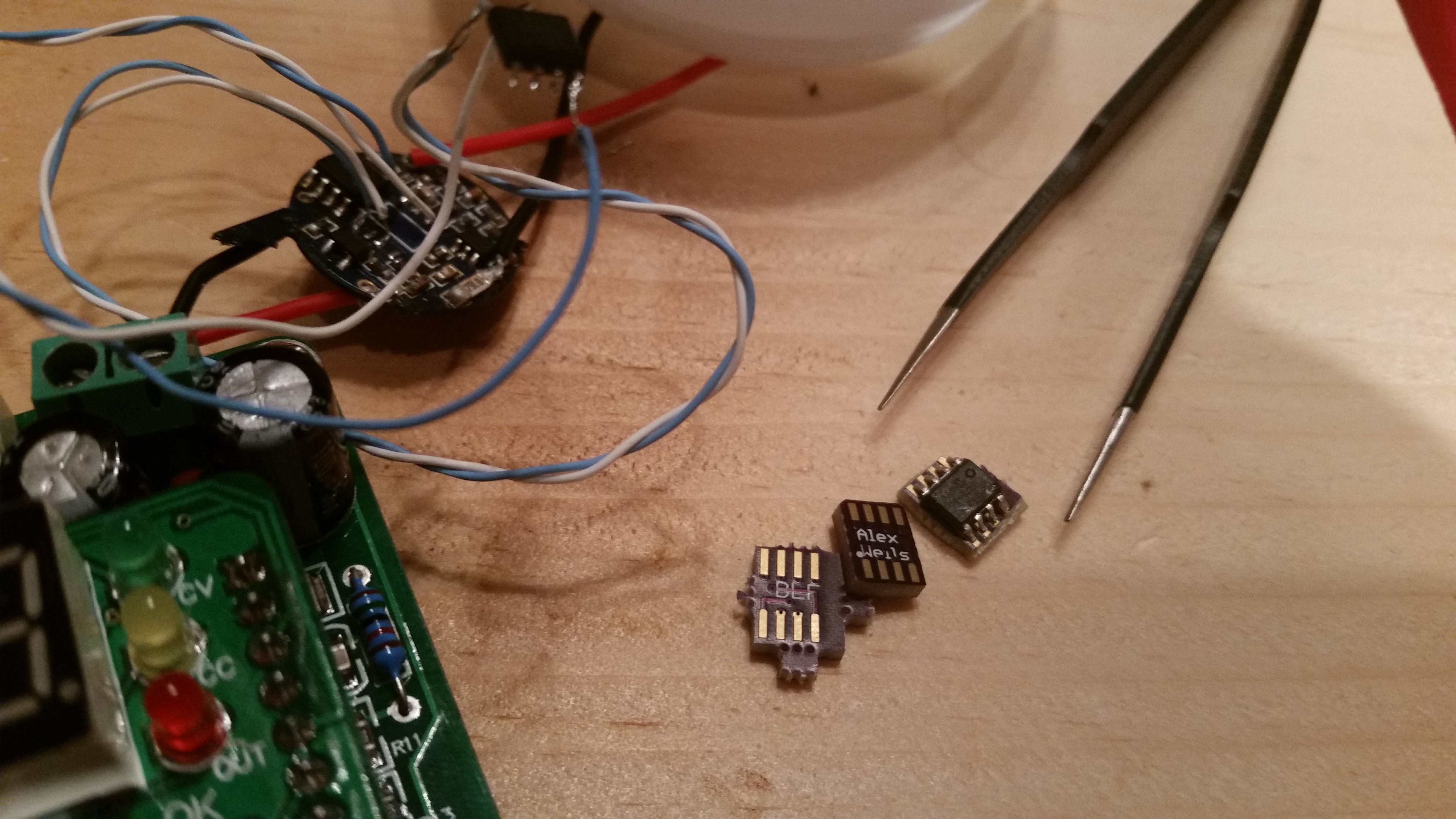
A tiny10 still takes up a lot of space and requires many air-wires in order to splice it into the stock driver (Vcc, GND, PWM, BAT+). An LD29 driver already wastes a fair amount of space since it must be installed with a contact board. See below for a picture of the first generation adapter boards. They do not work, I became confused when laying them out. I have already ordered replacements. These boards should just reflow in place of the stock PIC and lift the ATtiny up by that much. The whole assembly should remain shorter than the height of the inductor.
The new generation boards on OSH should work okay?
v06 should work. I’ll test one when I get them.
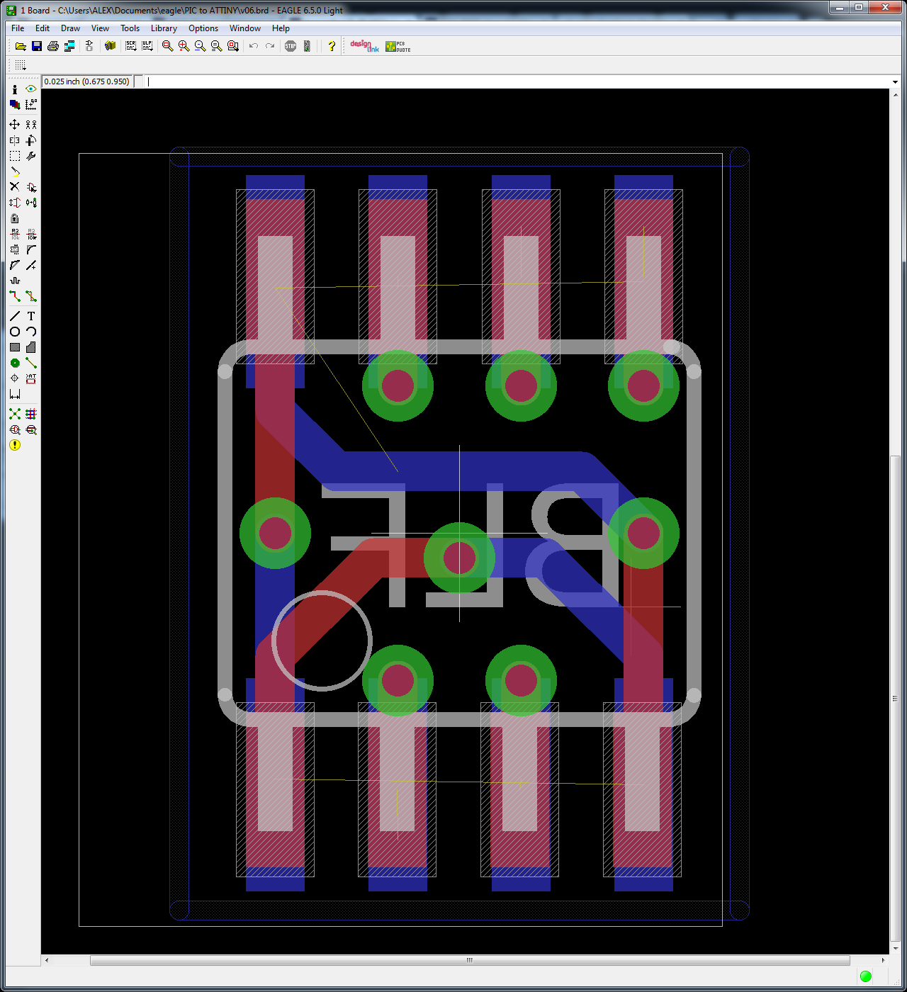
EDIT: Here is an Eagle screenshot showing both sides of the board. The ATtiny is on the red (top) layer, the bottom layer sits on the driver board. Pin 1 is marked with an empty white circle.
Is that real?
I paid 0.40$ for 3pcs incl. shipping.
Maybe they had a mistake on their website…
That’s what that little contact board was for in your OSHPark projects bin…awesome!
Will it need to be jumpered over to the old IC pads or are you going for a one for one dropin approach?
And no…teeny tiny boards are crazy cheap…this is why it’s only like $1.70 for 3x 15mm SK68 boards I designed
HiTiT wrote:
B.T.W
so without an MCU, this driver can work with a momentary switch connected between pin 3 to vcc and pin8 to vcc ?
I mean while pressed: light is on, otherwise: light is off.
OH MAN! I so like where you are going with that. I've always missed being able to do manual pulsing (e.g. Morse code, etc). I'm gonna add another momentary to my current mod for that. Thank you!
EDIT: Love the adapter board wight. Nice work. 
@ wight & WarHawk-AVG
Yep, it is totally cool! it is so easy doing mods with such prices.
No problem ![]() It might be a nice project!
It might be a nice project!
you may also use a reed switch instead of a clicky switch, it might be cooler - that’s what I plan to play with.
I have ordered some more components and LD-29.
I’ll try to make a nice mod when I receive it. H)
![]() I’m going for ‘dropin’. If we had to use jumper wires I’d just stick w/ a tiny10. You do have to file each one down. Once I had the non-functional v04’s in hand I filed down all 4 edges.
I’m going for ‘dropin’. If we had to use jumper wires I’d just stick w/ a tiny10. You do have to file each one down. Once I had the non-functional v04’s in hand I filed down all 4 edges.
Thanks guys. I must have been not in my right mind when I did v04 of the adapter board. Hopefully I’m in my right mind now. ![]() I’ve reviewed the board a couple of times and it v06 continues to look right, so I think we’re OK.
I’ve reviewed the board a couple of times and it v06 continues to look right, so I think we’re OK.
Since this PCB does not expose any of the bottom leads to your soldering iron I consider it similar to a MLF package. In my opinion the best way to install these is going to be hot air reflow onto a clean PIC landing pattern. Use desoldering braid to clean up all the old solder, then apply solder past, then reflow the PCB into position.
