v06 should work. I’ll test one when I get them.
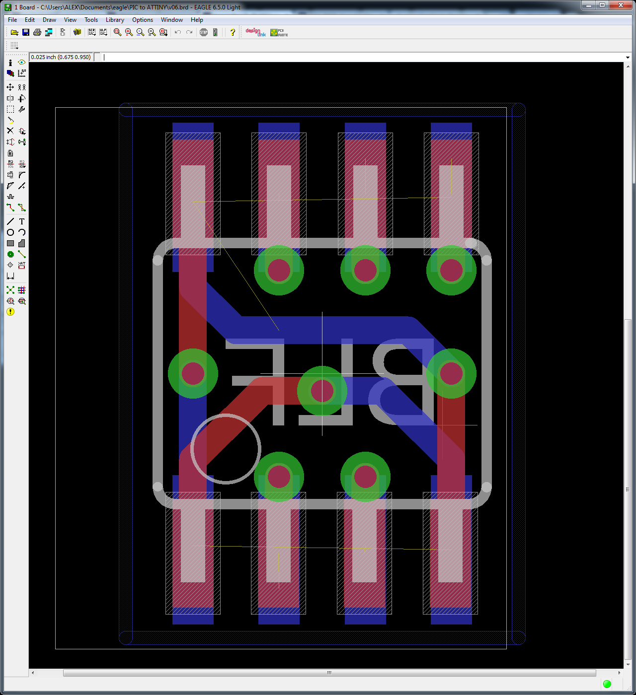
EDIT: Here is an Eagle screenshot showing both sides of the board. The ATtiny is on the red (top) layer, the bottom layer sits on the driver board. Pin 1 is marked with an empty white circle.
v06 should work. I’ll test one when I get them.
EDIT: Here is an Eagle screenshot showing both sides of the board. The ATtiny is on the red (top) layer, the bottom layer sits on the driver board. Pin 1 is marked with an empty white circle.
Is that real?
I paid 0.40$ for 3pcs incl. shipping.
Maybe they had a mistake on their website…
That’s what that little contact board was for in your OSHPark projects bin…awesome!
Will it need to be jumpered over to the old IC pads or are you going for a one for one dropin approach?
And no…teeny tiny boards are crazy cheap…this is why it’s only like $1.70 for 3x 15mm SK68 boards I designed
HiTiT wrote:
B.T.W
so without an MCU, this driver can work with a momentary switch connected between pin 3 to vcc and pin8 to vcc ?
I mean while pressed: light is on, otherwise: light is off.
OH MAN! I so like where you are going with that. I've always missed being able to do manual pulsing (e.g. Morse code, etc). I'm gonna add another momentary to my current mod for that. Thank you!
EDIT: Love the adapter board wight. Nice work. 
@ wight & WarHawk-AVG
Yep, it is totally cool! it is so easy doing mods with such prices.
No problem ![]() It might be a nice project!
It might be a nice project!
you may also use a reed switch instead of a clicky switch, it might be cooler - that’s what I plan to play with.
I have ordered some more components and LD-29.
I’ll try to make a nice mod when I receive it. H)
![]() I’m going for ‘dropin’. If we had to use jumper wires I’d just stick w/ a tiny10. You do have to file each one down. Once I had the non-functional v04’s in hand I filed down all 4 edges.
I’m going for ‘dropin’. If we had to use jumper wires I’d just stick w/ a tiny10. You do have to file each one down. Once I had the non-functional v04’s in hand I filed down all 4 edges.
Thanks guys. I must have been not in my right mind when I did v04 of the adapter board. Hopefully I’m in my right mind now. ![]() I’ve reviewed the board a couple of times and it v06 continues to look right, so I think we’re OK.
I’ve reviewed the board a couple of times and it v06 continues to look right, so I think we’re OK.
Since this PCB does not expose any of the bottom leads to your soldering iron I consider it similar to a MLF package. In my opinion the best way to install these is going to be hot air reflow onto a clean PIC landing pattern. Use desoldering braid to clean up all the old solder, then apply solder past, then reflow the PCB into position.
I was reviewing the pinout just now to do the required STAR firmware modifications and realized that there’s a small problem with the adapter PCB for this application. The offtime cap is on pin 6, which the adapter brings straight through (to pin 6 on the ATtiny13A). Unfortunately there is not an ADC on that pin, it cannot be used for offtime.
Also, it seems that hardware PWM is only available on Pin #’s 5 & 6! Lucky for us #5 is the PWM pin.
For the LD-29 Pin #2 is NC, so hooking the ATtiny up to that pin doesn’t do anything. Instead we’ll move Pin2 on the attiny to the #6 position on the PCB and not worry about losing any features. At this point the board is getting a little crowded:

Damn I ordered 6 of the v6’s literally 10 minutes ago!
Still should work or no?
Yeah, I expect it to work fine. You just can’t use the integrated offtime cap unless you do an airwire from Pin 2 to Pin 6.
Here is the v07 from the previous post - OSH Park ~
So I would wire a cap to the ATTiny pin2 (or just a jumper wire from pin2 to pin6 to use the on board cap)?
And this uses stock off-time FW or the ports need changed?
Thx
FW needs mods. I was planning to work on them tonight but haven’t gotten around to it yet. PWM out must change pins, ADC changes are needed for LVP.
Yes, you could just wire up the cap as you described.
I’m not 100% positive that we can easily do the offtime cap & battery monitoring at the same time using the stock setup, but we’ll see once I wade into it. The offtime cap needs to be compared against a lower reference voltage than Vcc, so we normally compare it to the 1.1v internal ref. The battery monitoring voltage divider needs to get compared to Vcc. We’ll see how that pans out! I think it will be OK.
Oops, this is just me being crazy again! Totally insane. The ADC doesn’t return a boolean value (maybe the comparator does?). The code is already fine to do both. Ugh, the things I say sometimes. The only thing we need to tweak is voltage we compare against and all the values.
Note to self: divider gives 1.2v @ 6v input
Well, I’ve gotten mixed results from the first offtime firmware effort. I should have done it in stages, but I made all my changes at once. Oops.
I changed everything I mentioned before:
Please review my changes here.
Oops, I see a problem already - I didn’t remove the STAR2_PIN = PB0 define from the code. I’m not sure if that’s causing any problems, but we are using PB0 for something else. I can’t imagine that it’s doing anything good.
The firmware fires up and runs the driver at 100% duty cycle but does not successfully change modes at all, ever. I even shorted VCC to PB3 using my tweezers and then cycled power to the driver a couple of times. I could not get it to change modes. Hopefully this is due to my mistake with the PWM output pin?
C_K wrote:
Damn I ordered 6 of the v6’s literally 10 minutes ago!
Contact OSH Park and ask them to subsitute in v07. I've done it before. They were really friendly and happy to accommodate.Still should work or no?
Wight I can air wire a 13A in and start on the coding with you but if I order an LD-29 from fasttech I’ll be waiting a month+, I have the worst luck with their shipping every single time I use them. Do you have a spare I can buy from you for testing purposes so I don’t have to sit around waiting?
I went ahead and ordered 6 v07’s I’m not concerns about asking them to swap them out for $.80. It’s not worth Lean’s time even tho I know he’d do it so I’m not even gonna ask.
Unfortunately I’m not in much better shape than you. I only have 1 available to work on currently. And I just lifted a pad on that one! It still works, but I need to be more careful. If I was in better shape we’d get you hooked up. Be sure to spend the extra few cents on USPS First-Class. I always do on FT orders. For a single LD29 it’s $1.44, for two LD29’s it’s $0.88, and for 4x LD29’s it’s free anyway…
I know what you mean. When we’re talking about <$3 for PCBs I try to order as soon as I suspect the layout might be ready to go. If it turns out I’m wrong, well. … sad face: I just re-order. It’s worth it to me to speed up the time to have them in hand and possibly learn that changes need to be made. At least that’s what I keep telling myself. How’s your Eagle learning process going?
For the record when I was testing yesterday I noticed that the driver gets plenty hot. Regardless of whether the components can handle it, I’d pot the thing for sure.
In addition to what Cereal_killer said, note that OSHPark is totally rolling right now. From what I’ve seen they are doing 2-4 panels per day currently, so when you order you’d only have a tiny window to ask them to do manual corrections for you.
Was just trying to offer a friendly solution. C_K seemed upset about just ordering v06. No good deed goes . . .
