C_K wrote:
Damn I ordered 6 of the v6’s literally 10 minutes ago!
Contact OSH Park and ask them to subsitute in v07. I've done it before. They were really friendly and happy to accommodate.Still should work or no?
C_K wrote:
Damn I ordered 6 of the v6’s literally 10 minutes ago!
Contact OSH Park and ask them to subsitute in v07. I've done it before. They were really friendly and happy to accommodate.Still should work or no?
Wight I can air wire a 13A in and start on the coding with you but if I order an LD-29 from fasttech I’ll be waiting a month+, I have the worst luck with their shipping every single time I use them. Do you have a spare I can buy from you for testing purposes so I don’t have to sit around waiting?
I went ahead and ordered 6 v07’s I’m not concerns about asking them to swap them out for $.80. It’s not worth Lean’s time even tho I know he’d do it so I’m not even gonna ask.
Unfortunately I’m not in much better shape than you. I only have 1 available to work on currently. And I just lifted a pad on that one! It still works, but I need to be more careful. If I was in better shape we’d get you hooked up. Be sure to spend the extra few cents on USPS First-Class. I always do on FT orders. For a single LD29 it’s $1.44, for two LD29’s it’s $0.88, and for 4x LD29’s it’s free anyway…
I know what you mean. When we’re talking about <$3 for PCBs I try to order as soon as I suspect the layout might be ready to go. If it turns out I’m wrong, well. … sad face: I just re-order. It’s worth it to me to speed up the time to have them in hand and possibly learn that changes need to be made. At least that’s what I keep telling myself. How’s your Eagle learning process going?
For the record when I was testing yesterday I noticed that the driver gets plenty hot. Regardless of whether the components can handle it, I’d pot the thing for sure.
In addition to what Cereal_killer said, note that OSHPark is totally rolling right now. From what I’ve seen they are doing 2-4 panels per day currently, so when you order you’d only have a tiny window to ask them to do manual corrections for you.
Was just trying to offer a friendly solution. C_K seemed upset about just ordering v06. No good deed goes . . .
That was just an FYI, not a reprimand! ![]()
Did you notice what components got hot?
I was doing other stuff, so I did not pay close attention to that. I only worked on the bottom side. On the bottom side, it seemed to me that the FET and sense resistor both got hot. The sense resistor became hot faster I think.
:~ strange, both of the FETs’ are rated >8A on their datasheets.
I assume that it should’nt get really hot on ~2.8A ;\
[quote=HiTiT]
:~ strange, both of the FETs’ are rated >8A on their datasheets.
I assume that it should’nt get really hot on ~2.8A ;\/quote] I was working on measuring other stuff. Soon I’ll take a closer look at where the heat is really coming from.
I’d say that at 100% duty cycle this driver produces a good bit more than 2.8A out, although I have not measured. Probably around 3.5A+ output. The input at 8.2v (IIRC) was ~1.85A. That’s 15.17W input, so make whatever efficiency assumptions you want (80-90%) and figure the output based on that.
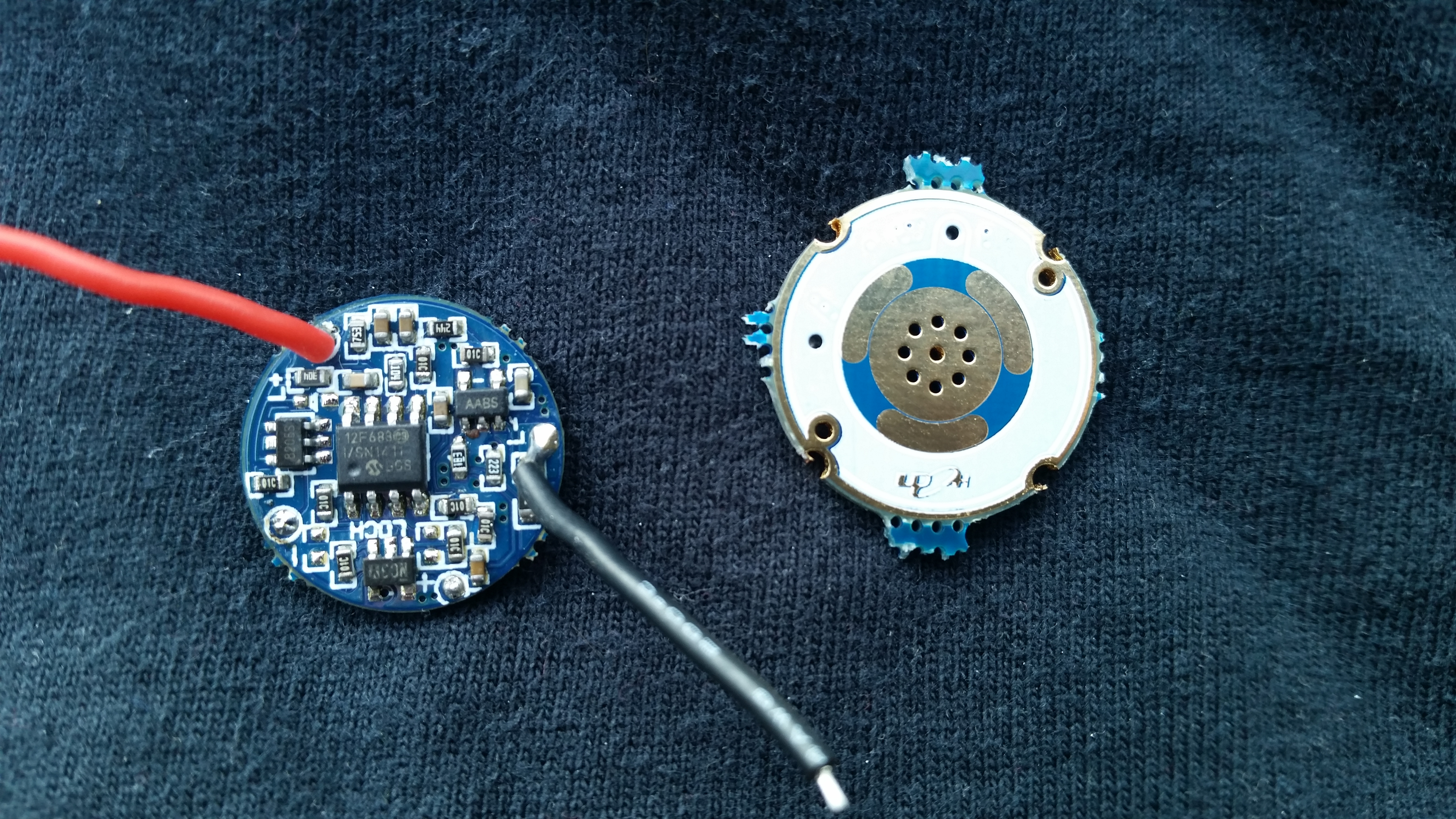
I dug this up just to post I found out what the black SMD component was, it’s when a SMD cap and resistor have a love child no seriously its a component called a ferrite bead.
Also my v06 boards are coming so I expect the 07’s to be a day two behind, as is usual with FT I don’t expect the driver till around middle to late August.
As far as I can tell an SMD ferrite bead would be a choke. I do not think that the component is a choke. If it was a choke I think resistance should be lower than 100k. Take a look at the DC resistance figures for some. They are ~100ohm or so and as I said in the OP this component is 100 k ohm.
My v07’s shipped yesterday!
A member here graciously sent me an extra LD-29. A good thing since mine is getting a little worse for the wear (from moving the PIC on and off, soldering wires to the pads, etc). Anyway it was ordered from FT on the 8th and arrived on the 17th with USPS - so 9 days from start to finish.
The new version LD29’s are somewhat different. I’m not yet sure what the implication of this is.
It seems to me that IRF7821 was replaced with the tiny 8205S, but I have not looked into this closely.
SBM1040 is a 5A continuous diode in the Powermite 3 package. This package seems to be about the same size as PowerDi 5 but may be superior? I’m not sure that Powermite3 is actually superior to PowerDi5, but it’s definitely a modern high power diode so that’s good. The old diode was marked 3912 and I have no idea exactly what it was rated for. Maybe 3A, who knows. The new diode is certainly better!
The 4435 FET I assume to be a 30V P-Channel trench MOSFET. The new one is marked 4435AG and the old one was simply marked 4435.
Come to think of it, I do not see a buck controller on either the old board or the new board. There are no sanded components and nothing jumps out at me as a buck controller. Odd. I’ll have to follow the CSN trace and see where it goes from the sense resistor. I wonder if it’s going through a current sense amp and feeding directly to the PIC. If so, we need a whole new firmware ![]()

Your new one’s from FT? My two shipped out yesterday ,I wonder which they’ll be.
I know about the good high res pic’s in the review, could you possible post a comparison shot of the two drivers physically sitting right next to each other orientated the same please?
I’m just wondering cause I’ll be ordering a PICkit3 this friday (I have 3 current projects centered around PIC MCU’s, I’ll probably be pretty much completely switching here as soon as I can and redesigning the 17dd for the 8kb PIC MCU of my choice) but is the only reason for all this to be able to program these with no additional equipment from the other AVR programming we all do? Is the MCU not able to be flashed (with the correct PIC equipment) cause its locked or something?
First of all: sorry Cereal_killer, I have no immediate plans for more photos. I’m really off of taking pictures right now. That’s why I’ve only been using my phone and only posting shots I deemed necessary. Also I don’t have a stock LD-29 available to put it next to.
That said, there’s really nothing you need to know that you can’t glean from what I wrote and the pictures I took.
I have no idea what the state of the PIC controller is.
My new one is from FT. I’m sure you’ll get the same thing, the listing on FT actually says that it’s the updated version.
I have not taken an in-depth look into the matter, but my current assumption is that the new version is just a simple refactor to make better use of space with the savings from going SO8 to SOT23-6 on that N-Channel FET.
May I ask what motivated your switch from Atmel to Microchip?
Hey man, can you post / email me the FW you have that gets the driver to run high only? I tried this (both as-is and after removing the STAR2_PIN=PB0 and references to it).
Also what way does the adapter go on? with the pin1 dot up and in the factory orientation and the 13A pin1 goes aligns with that?
Hey Cereal_killer, let me review the facts this weekend and make sure I don’t tell you a lie ;-). I haven’t worked on this in a little bit and I’m getting fuzzy myself. I have yet to install any of these PCBs (I have v6 and v7 in hand though). I just had the thing hard-wired, even worse than dead-bug style.
For now I’ll tell you what I think I know:
Somewhere in this thread I/we discuss how to turn the driver on. There appears to be both an enable pin and a PWM pin. Just pull the enable pin high or low, whatever I said earlier, and then pull the PWM pin high… that’s 100% duty cycle, a state the stock firmware never allows AFAIK. Sorry for the brevity and lack of details, I’m pretty limited on the computer front right now.
Frankly I don’t recall if the pin configuration for that firmware matches the pin configuration for the v7 adapters. I will check into this.
I have measured the PWM frequency on LOW using the new LD-29 I recently posted pictures of. I measured the period to be 76us, which should be approximately 13kHz. This isn’t visible in the output signal, but we want to be in that general range w/ the output from our ATtiny.
My scope is not in good shape, so this is questionable, but it appears that the buck section is operating at around 444kHz (XM-L2 on the output, 8v on the input, medium mode).