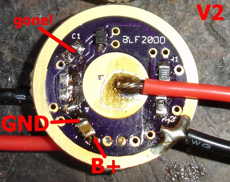
YES AOD510 WORKS WITH NO GATE RESISTOR* AFTER MOVING C1 TO B+/GND! All of them work with no gate resistor after moving the cap. Even the 15DD with the IRLM2502 works with no gate resistor after moving C1.
*replaced with a jumper on the versions with gate/pulldown pads, pulldown location left open, of course
Since getting my 858D station yesterday I’ve built 6 17dd’s (5 this new way and one zener modded), 3 of them with the AOD510’s and 2 with the old Vishay’s are working fine however the one with the one FET I have out of an M6 is giving me some issues with the exact same firmware. It’s heving problems when cycling threw the modes, after turbo sometimes it’ll miss moonlight completely and just go back to low (5-mode off-time with no memory and moon defaulted on without the star needing to be soldered), other times it will go to moon but with a bad preflash.
I’m not really complaining, I have exactly one of these FET’s and dont really mind discarding it to the random parts drawer, just reporting my findings.
What's the p/n on the problem FET? Curious to find a datasheet on it and see what it has in the section for gate characteristics. Both the 70N02 & AOD510 have a total gate charge number known to be something the attiny is capable of driving. Above something like Qg=40 they can get troublesome, or at least that's the general number I've heard to stay under.
This is really great stuff you’ve found out CC and precisely the kind of thing that only comes out after new ideas are tried out and someone takes the time to troubleshoot odd behavior. Good job.
So as it turns out the zener modded driver do in fact have the issue, I of course dont have a scope to know if its the very same issue but it was giving me identical behavior where it skipped modes or shut its self down or just overall acted bad when I tried building it with R3 jumpered and C1 populated like normal (with the 10uf cap and the zener diode) and a R200 in place of the protection diode and it did turn on but neither luxdrv fast or phase correct (its known that fet drivers still need luxdrv to run at phase correct PWM) nor my custom weapon mounted UI were usable with it like that. This is in my MT-G2 ZY-T08.
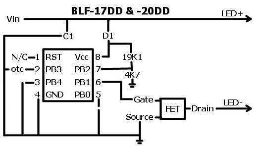
Took it back apart replaced the jumper at R3 with a 130 and populated R4 with a 10k and the light worked perfect with both FW’s!
Brings back the question, can I put the zener diode on the C1 pad with no C1 and put the 10uf cap from batt+ to like with the non-zener ones or does the zener diode REQUIRE the cap to be there?
Most certainly not the case! Only the momentary switch firmwares, that use a different 'sleep' method, require phase correct FW (and that holds true whether it's a FET or 7135s). I built many many lights with FET drivers running luxdrv converted to fast-PWM.
The zener and the cap aren't directly related, they just got piggybacked because they both required connections to the same points. If moving the cap fixes it (which I doubt, since without the normal diode at D1 there is no longer a voltage boosting situation) then that's fine.
Can I send you the exact .c and hex files I have for luxdrv? When I try changing it to fast and putting it on any of the FET drivers it doesn’t run, or can you send me your file so I can try it?
Fast or slow will work on my 105c (and other 7135 drivers) but this version luxdrv fastPWM doesn’t work on my FET drivers.
Currently the light is running with all resistor pads populated and slowPWM and it didn’t run with R3 jumpered. Ignoring for a second the FW issue fast vs. slow, what should I do with it, leave it as-is or move the cap down to where I am using for 3v ones (your v2 pic) and re-jumper R3?
@ CC: Your are my hero. And every other modder wanting to be mean to led lights. I never would have thought about getting this heavy into the electronic part of the hobby if it was not for you. TY :-)
does anybody happen to have screen shots or images that were posted by comfychair? trying to learn more about the whole C1 cap placement decision on the current iterations of the BLF 17DD.
thanks that does help me with the history. I was specifically curious about how noisy the Vcc line gets with the current C1 cap placement since the screenshots are missing. From what I can tell in the comments of this thread there may be noise/spikes with the current C1 cap placement but it was deemed acceptable. Also, I’m still wondering why the gate resistor was deleted if it could have helped with the spikes as well. Guess I need a scope and more studying :party:
I’ve been having an issue with a driver built from a wight board running star firmware. When running a triple XPL at high current I’ve been having issues with the driver flickering and shutting down. High current being bypassed springs with LG HE2 cells. Nonbypassed springs or tamer cells don’t seem to have this problem so I was looking here for clues :bigsmile:
From memory, the revised C1 placement cleaned up the spike greatly.
That’s interesting, I’m having the same problem with one of the 17mm DD MTN drivers, which is pretty much the same as Wight’s board.
Does your problem driver also switch off if you run it on low for a few seconds?
I know the design of these boards are proven, as there are hundreds of them out there, & I’ve built plenty before this one, but it’s still a pain when you can’t put your finger on a particular issue…
Weird - I'm using a wight FET+1*7135 driver with the SIR800DP in a triple XPL X6 getting 10 amps with all heavy bypass wires, etc. Basically works well but I got one noticeable issue and it's a blink when changing modes to moon mood, fron turbo or not. RMM recommended trying a resisotr off the FET gate, like a 100K or so -- didn't try that yet.
yeah the problem will happen in low it will flicker a bit and then shut off a lot of times. really only in a high current situation though. I can’t remember if it was medium and high too, but definitely low.
my parts are from RMM so I think this driver is a NXP PSMN2R4-30YLDX FET. have some SIR800DP but haven’t tried those yet. I don’t think the FET choice is an issue though.
funny you should mention the gate resistor because that did seem to be a good thing from this discussion, so I was trying to understand why it was removed from the design in the first place. parts count reasons?
I actually added a 200ohm resistor (replaced the existing diode) and a zener along with a second 10uF cap in parallel with the zenner (also all known as the zener mod - but still running as single cell). C1 still has 10uF cap as well. This was discussed earlier in the thread as a possibility of smoothing out the Vcc line.
To be honest I haven’t been able to get my light to act up again after doing the zener mod with this single cell driver. It was pretty easy to reproduce the behavior before I added the zener. I would like to try the gate resistor at some point too (without the zener). I will probably build another driver and keep tinkering. I’ll update if my driver acts up again.