Thanks. Got the stuff to program, just have not tried it yet. Ill get to it since I now have a reason to do some tweaks.
What have changed since you now can use fast PWM? And why isn't Richard selling these with fast PWM?
Thanks. Got the stuff to program, just have not tried it yet. Ill get to it since I now have a reason to do some tweaks.
What have changed since you now can use fast PWM? And why isn't Richard selling these with fast PWM?
Ohhh - I'm still using phase correct but these ol ears can't hear it.. Hhmm - gonna have to change. Forgot details how to convert and not sure of side effects - still can use low PWM value of 1?
Previously DrJones was the only one doing FW for momentary drivers, and the 'sleep' method he uses means the LEDs do not turn off completely in the 0% mode (that's the only way to turn off a momentary driver since the +/- remains connected at all times). Jonny does something different in his code (which of course I don't understand) that fully puts the MCU to sleep after the button is released. None of that matters or has ever affected the clicky drivers.
OP updated with latest BLF17DD board link and parts list. Added links and post #'s to get ref info from the gi-normous OSHPark thread.
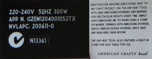
Awesome info and tutorial. Thank you Tom E.
I've been shopping at our local Spotlight and come home with this. Before I open it do you guys think this will do the job. Apart from the color it appears identical to the one Tom E linked to earlier.

Still very new to DIY drivers and seems like it is really cool! Can someone tell me a little about this driver’s specs? RMM’s site does not really provide enough info, like how many amps, input voltage, etc. I really want to build one because it is called BLF! Thanks for your help!
It is direct drive like the now obsolete/out of production east-092, but with an easily reflashed controller. So depending on what firmware you give it, it'll work in either clicky switch lights or momentary electronic switch lights. The number & level of modes and the PWM frequency all depends on which firmware you use.
The FET (basically just like a relay, but with no moving parts) has been chosen to give the lowest possible resistance, so with a hot INR/IMR cell you'll see something like 6.5-7 amps to a single XML2, or 11-12A to a triple from a single cell.
Interesting… Thank you for the explanation. Would I need something like what Tido (https://budgetlightforum.com/t/-/744 ) has to program the firmware?
One question that I am interested in is the momentary switch. How do I use these? They are rated .5A and do not stay on after I press on them. Does the FET turn on and off every time there is an electrical connection or something? These switches are SO tiny, versatile, and come in METAL! O:
The momentary switch only grounds one tiny pin on the MCU, it doesn't carry any current. The firmware in the MCU monitors that pin for button presses and then follows its instructions on what it should do. Power & ground are always connected at all times, the MCU turns the FET on or off (pr pulsed at a very fast rate to give the lower modes). When the FET is off, no current flows.
MRsDNF - it does sure look the same. Hope the heat and airflow are the same though.. Guess this is kind of a risk though because there's no specs to speak on these things, besides the wattage I suppose, and the 300W rating does match mine.
Mine is stickered with: Heat Blow Tool, 300W 120v/60hz. Model: HG-100, Made in Taiwan
But it doesn't have the official description that yours has: BADA-BING, BADA-BOOM, so yours must be better  .
.
When I first saw this post there was no description and I thought MRsDNF was having marital problems.
What would be a good size nozzle outlet to make for it as its quite large the way it is? There probably is marital problems OF but me being the guy will be the last to know.
Dunno if it can take a nozzle - I use it as is.
MRsDNF likes attachments on his toys…
Has anyone tried these DD FET based drivers using 4S AA Eneloops and a single xml emitter?
Wondering if the voltage would sag enough for an emitter on copper to survive.
Probably same as a Nanjg - if the MCU can take it - is it a total of 6V fully charged? If so, on the borderline for the MCU - might need the zener mod. I would think a FET DD or 7135 driver would have the same issues? Dunno details, but I believe the LED will take what voltage it needs from the cell - for example using a 4.2v charged cell is too high for the LED, but it still works fine, but there must a high voltage limit for the LED... Not sure off hand - probably on the CREE spec sheets.
At 7amps a full eneloop AA sags to ~1.1V (HKJ's results), that is 4.4V for four in series. At 7amps a xml2 on copper needs 4V, so with no resistances the current will be more than 7 amps. But there will be resistance, especially with cells in series, so you might just get away with it and have a very nice DD- light :-)
But I don't know what voltage the mcu gets for a brief moment at startup, might be the full 5.4V, and still should survive that.
Thanks Tom E and djozz. I should have thought to look through HKJ's work for eneloop voltage charts.
Yeah, it might be better if I reserve 4AA to a multi-emitter application. It's just too hard for me to not try to take all the resistance I can out of a light. Even if it needs some. Some type of OCDitus, I guess.
Back to topic - I ordered qty 6 of these BLF17DD V1.0 boards today, so couple of weeks I'll post detailed pics.