DayLighter, you’ve also got a point. I didn’t make a 16*7135 driver because I thought it was a good idea to run the light at 5.6A/6.08A. I made it because I wanted a 22mm 7135 driver with the features this one has… and I just put as many 7135 as I could fit. It’s great that it turned out being 16* because that lets you put 8* all on one side if that’s what you want.
Populating all the spaces get’s way more useful if I was to implement what I wrote about over here. With 16* and 4 pins I think you miss a count in there, for example the 8x count: (1,2,3,4,5,6,7, _ ,9,10,11,12,13,14,15,16). Anyway with a setup like that, which there is probably room for on this board, you can keep all your normal modes running at an actual regulated current instead of PWM (so you’d have improved dropout and efficiency I think) and you can set your turbo or strobe modes to use all of the 7135s. Maybe it makes more sense to do that with a big FET.
Saaweet! How did I miss this thread alltogether?? Great work Wight! And sweet looking board Cereal_killer :-) Did you populate all the amc spaces or not? I'd love to hear how that host handles it if you did ;-)
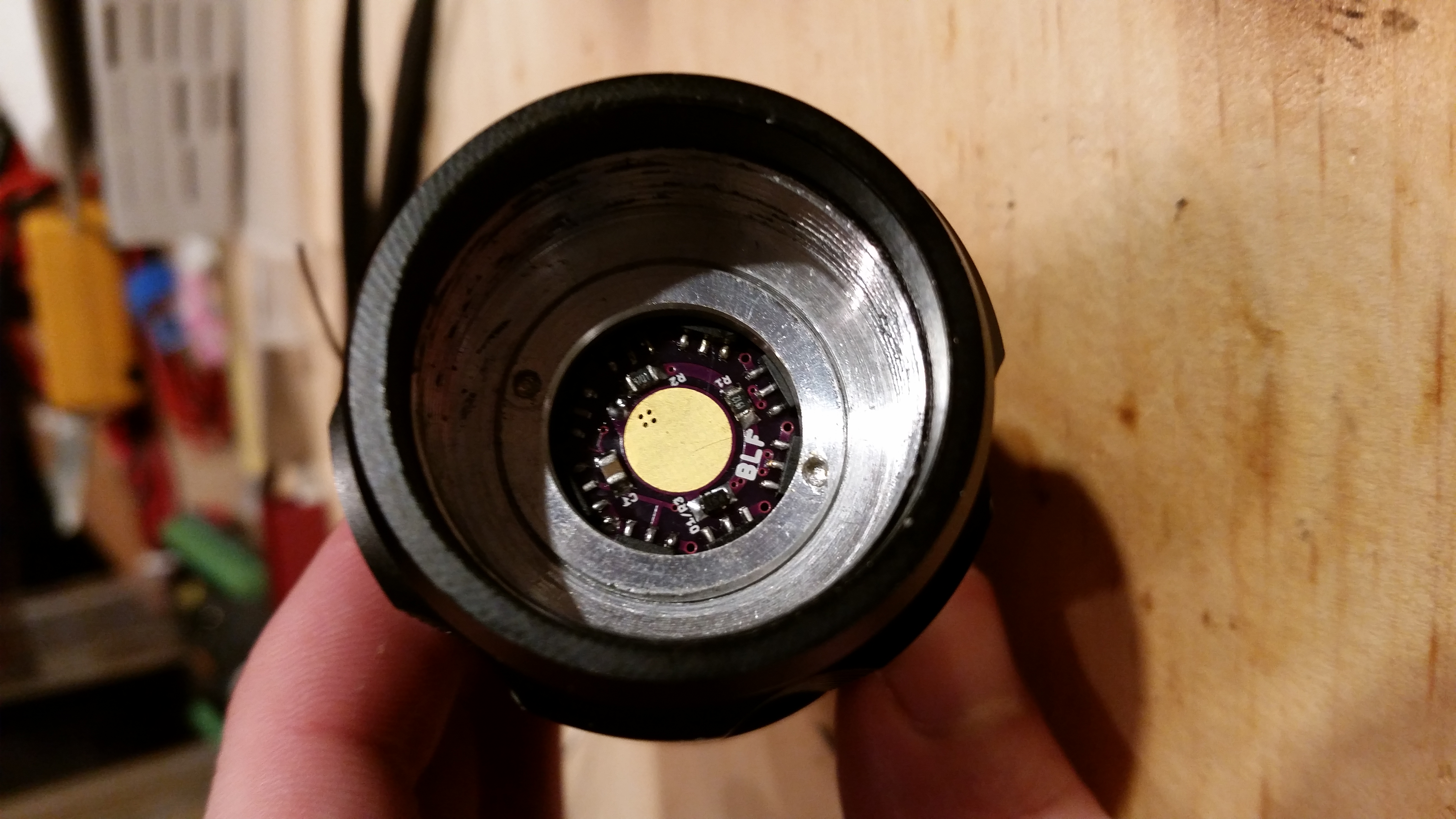
I didn’t, the host I’m using (not the F13) requires a thin 14mm MCPCB and a turned down Noctigon / sinkPAD is simply to thick to allow the head to screw far enough on to get the emitter into the reflector (an rii E21- balder SE2 clone with very strange reflector/pill design) so I’m only driving it at 3.04A. If I can get another light to take this board I’d love to fill one up with 16 chips, even stack some more if there’s room, imagine a 17-32x board that only takes a single layer of stacking.
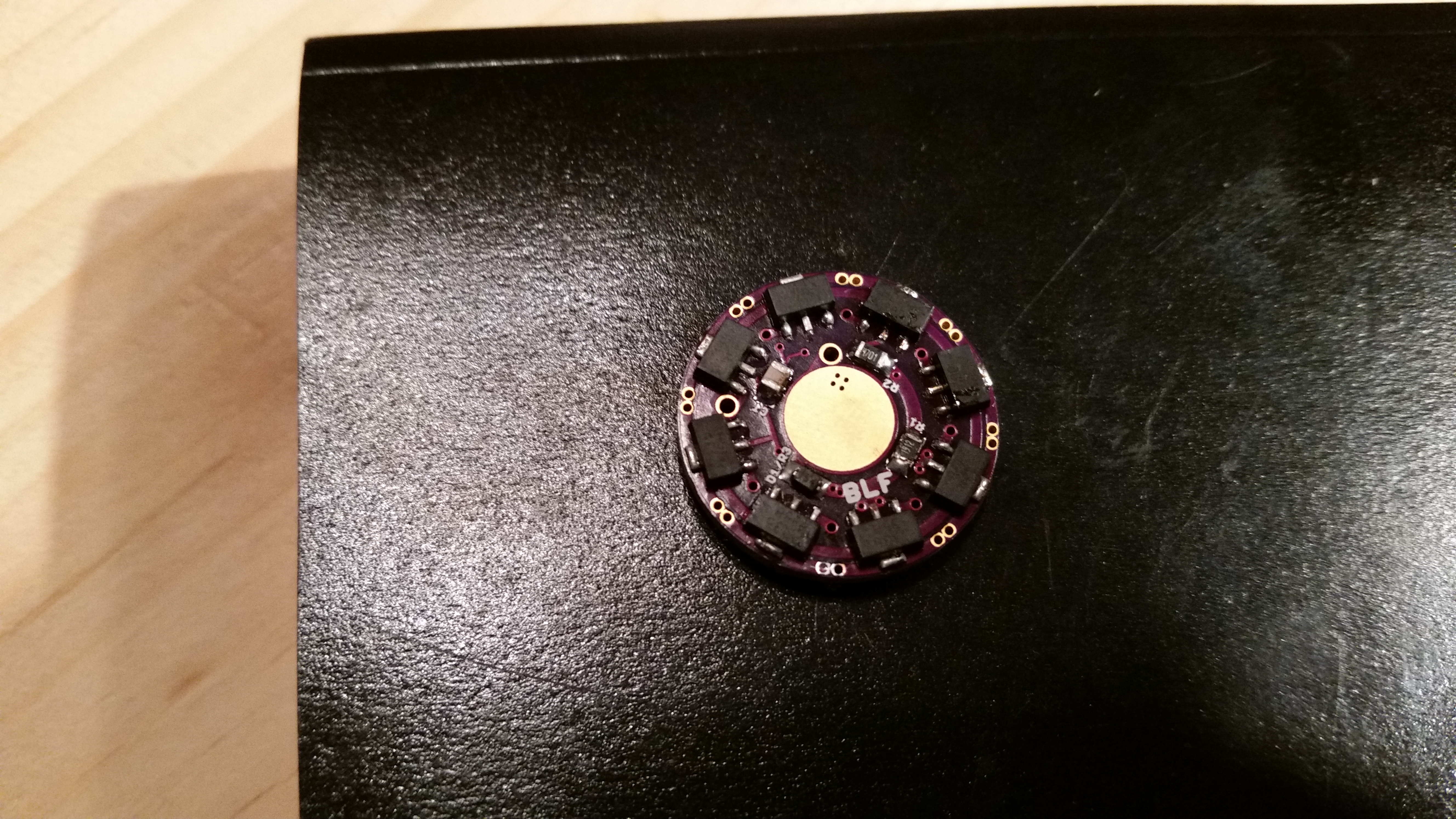
I have installed & tested this driver in a Gearbest Ultrafire F13. I populated it with 12x7135, 8 on the bottom and 4 on the top. I made sure to populate the space right next to the offtime cap so that we could see how tricky that got. As I mentioned earlier, the spacing of the 7135’s on top is such that the tabs miss the shelf, allowing the driver PCB to fully seat against the shelf.
I think that I intended for the LED+ / LED- vias to take 20AWG but they do not. 24AWG fits with room to spare. I may release a revision to address this, but there’s very little space left! Probably better to file down 20AWG if you want it to fit.
Sorry for the cellphone pics.
Now that I have built v015, I feel confident that the board is ready for prime time. I have revised the silkscreen for C1 and released v016. There are no functional changes from v015.
I made a mistake with the firmware. I started with STAR_off_time_1.3.c. I disabled moon mode through the define (commented it out). I also reversed the if/then terms for Star 3 since I don’t solder stars and wanted H-L. Apparently I did something wrong because I ended up with L-H. Come to think of it I still don’t see my mistake. Oh well, I’ll take a closer look later. Maybe I shorted the pin on the MCU.
Thanks for the complements on the build. It needs a tall battery spring, I started with a Nanjg 105c spring and it was way too short. I switched to the D-type spring (5/8/8/0.8mm) from IOS and it was barely enough. I’ll have to install a tall post I think.
Somehow I lost track of it in the process, just stumbled over it through the oshpark thread.
This is like a one-that-fits-all driver, including the BLF add-ons off-time memory and zener mod.
Thanks for that one.
Errr… would you mind sharing the brd-file if you happen to have one?
I need that driver slightly larger (24mm) and would adapt it. But I have no software to alter the gerber files, just Eagle here.
Tbh, I’m thinkin’ of some other minor tweak 0:) (12x 7135 suits me well, that might give room for a larger spring base to fit IOS type A, B and D)
Thanks Cereal_killer. I’m still really not “in the saddle” at the moment. I’m really just treading water waiting to get motivated ;). I was losing steam and right as I got my new scope and a box of supplies from Mouser I just stalled completely. :( Hopefully something will click in my head pretty soon and I’ll sit down and get a 20mm buck driver knocked out, verify that it works as expected w/ the Attiny installed, release that, and then refocus on the 17mm stuff. EDIT: having spares on hand is a key part of my motivation process, and I’ve got that in spades. I think I bought 10x worth of parts from Mouser plus a few alternative parts. And I think I’ve got 20 of those QX5241 chips on hand, so I’m ready to fry some stuff as soon as I can get that switch flipped in my brain.
I’m amazed at what several of the guys on this forum are doing with designing and building all these custom drivers! I’m going to need a driver for one of the projects I’m working on, but I don’t know what size or even shape it will be. But, anyway, this one looks awesome! Great job, wight!
I hear that Alex, unfourtinately I don’t have the option to take a break with how my business has evolved…
Btw I have a new 2-4 cell buck driver based on the MAX16824 chip. Output is selectable to around 8A (for 3-9v emitters/strings) via sense resistor. PIC controlled but it could be easily adapted to AVR (with the addition of a vdivide circuit for batt monitoring and a few cap changes). Very stable operation with the inducer I selected, much easier on 3v emitters than the HX-1175b’s at high currents and with pic Very low component count so cheap to produce. I’m working on a larger one initially, hopefully I can get it to a 20mm single board (not sure tho) or a 17mm double stack <12mm tall.
I think I might get testosterone shots or something…so dang demotivated…
I need someone to put on a DI hat and yell at me to get my butt moving as of late…sux, so tired, so moody, so sluggish and unmovtivated…ARRRRGH
I also am eagerly awaiting the 20mm buck driver, I have one of those 3x “C” Defiant flashlights, could definitely use a good driver and stack some 26650’s w/ spacer in the badboy
IIRC 26650’s wont fit in a DST, and boring it removes the tail threads. I think the normal solution is to permanently attach the tail after that and load the batteries from the front of the tube?