He’s sent me the links. I’ll update the op ASAP.
sorry…they are under my profile…Rufus is going to fix the links…I did a revision tweak like on the BLF17/20/22 and moved the C1 capacitor (for the mode change stability) and removed the load resistor
Sorry about that…
RBD - I have released my 22mm 16*7135 driver for F13 flashlights.
Can anyone give me the voltage divider resistor’s the CAP and diode values for the MELV2? I’m building my next board now based of everett’s PIC MCU but dont know what the values need to be.
Have you checked his discussion thread? If it’s not there, you’ll have to pm him as it’s not a nanjg component set. You’ll find his email there too.
I havent checked but I email the crap outta him (I’ve already sent him 3 emails today lol) so I was hoping someone here would know so I dont have to bother him, he’s already working on a few projects of mine as is.
I can start designing now using 0603 pads, I just need to know before ordering parts.
You might need to send out an APB on the general forum then to find someone who’s assembled one. Good Hunting.
Hold up I'll tell you.
EDIT: Wait - you mean the component sizes or the actual resistance, capacitance etc?
I think he wants the actual R values and Cap values.
Does this help: https://www.dropbox.com/s/p95zp9rls8i7o1f/MELD%20v2.pdf
I can't actually see a voltage divider on that circuit...
That may be, that would mean the MCU could monitor the voltage all by its self then? Since his UI offers voltage readout by flashing one of the channels how else could it do that?
Before I started eagle he built me a single li-ion, 3ch driver using 7135’s, the ONLY components are the MCU, the 7135’s and one single cap so I guess it can do it internally.
Yup its done internally on the PICs. Can be done on AVR chips but normally the higher end ones.
Guys I just want to say a huge thank you to Mattus, WarHawk, ComfyChair, RMM and RBD for all the work they do, everyone please take a moment to check out my 1k post /1 year GAW thread and help nominate the last 2 winners and check out the custom engraved lights they’ll received.
Special thanks to Calvin at Illumn, Ric at CNQG and Richard at MtnElectronics for helping make the prizes what they are, couldn’t have done it without any of them!
The Medusa PCB works (albeit the version I'm testing required a physical modification that will corrected in the next revision). I'm not sure if people are interested but I'll upload the revised PCB to OSHPark later tonight.

For what it's worth I have not used a 70N02 FET. I have used a IRLR8721PBF. Seems to work fine - has no problems performing the diming or strobe functions of tterev3's firmware.
- Matt
Matt. I say this as a forum friend to save you any more embarrassment here, can you please make sure your soldering gets a little more practice. I'm not saying its bad just not quite up to standard. I'm glad I also told you that you would have to do a (s)light mod to get it working to save you frustration and the substitute fet to use.
Ok The above is BS. Its just my way of saying what an outstanding effort and l have no idea what any of it is. You sir are one amazing talented guy. Do paint fumes help with your creative juices? Can you let us know again what host and batteries you are using here? Cheers. Orsm orsm effort.
Edit. The wheelbarrow was full when I got out there.
I thought you were serious for a second because the wire solder joints are HORRIBLE. I broke my temp controlled iron and have been using a crappy iron from Dick Smith's (borrowed from my father) until I can afford a new station. I might still take this into work tomorrow and clean it up 
It's for a Sky Ray King. I've got the host apart and ready to wire up. I was going to have an 18350 tube machined by sinner so that it'd be a stubby SRK, but I need to stop spending money for a while. Maybe I'll get into the BLF spirit and 'chop' the 18650 tube. Then again if I bugger it up I'll be left with a head and no tube...
You’ll have a spare head for your next tube. ![]()
In the OP you have noted that these boards by Helios are untested.
https://oshpark.com/shared_projects/H63c8d5q
https://oshpark.com/shared_projects/XMtGKfm3
I've made a battery carrier out of these items and they work like a charm. I tested on a run of 5 amps output on 8 x AA NiMh on an MTG-2 was very happy with the way it worked. The only change I would make if any were to be made would be to add a center hole in the center of the positive end the same as the negative one. This is to allow a non conductive rod to be located with tiny nubs on the end that fit in these holes and locate the rod.
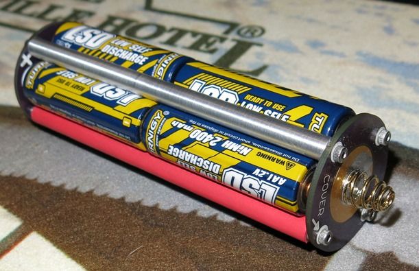
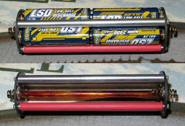
Looks good! And it is nice to see that if the carrier is done right, you can run a MT-G2 at 5 amps on a stack of NiMh cells (for half an hour at least)
19 minutes was the max. At 20 minutes it was all over.