Matt. I say this as a forum friend to save you any more embarrassment here, can you please make sure your soldering gets a little more practice. I'm not saying its bad just not quite up to standard. I'm glad I also told you that you would have to do a (s)light mod to get it working to save you frustration and the substitute fet to use.
Ok The above is BS. Its just my way of saying what an outstanding effort and l have no idea what any of it is. You sir are one amazing talented guy. Do paint fumes help with your creative juices? Can you let us know again what host and batteries you are using here? Cheers. Orsm orsm effort.
Edit. The wheelbarrow was full when I got out there.
I thought you were serious for a second because the wire solder joints are HORRIBLE. I broke my temp controlled iron and have been using a crappy iron from Dick Smith's (borrowed from my father) until I can afford a new station. I might still take this into work tomorrow and clean it up
It's for a Sky Ray King. I've got the host apart and ready to wire up. I was going to have an 18350 tube machined by sinner so that it'd be a stubby SRK, but I need to stop spending money for a while. Maybe I'll get into the BLF spirit and 'chop' the 18650 tube. Then again if I bugger it up I'll be left with a head and no tube...
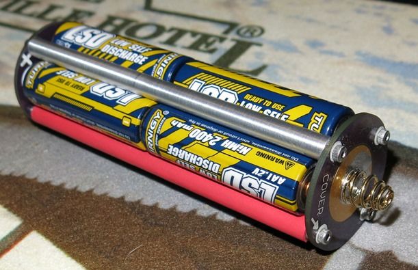
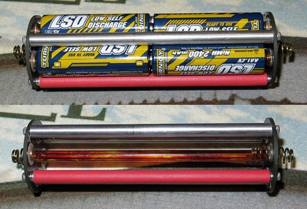
I've made a battery carrier out of these items and they work like a charm. I tested on a run of 5 amps output on 8 x AA NiMh on an MTG-2 was very happy with the way it worked. The only change I would make if any were to be made would be to add a center hole in the center of the positive end the same as the negative one. This is to allow a non conductive rod to be located with tiny nubs on the end that fit in these holes and locate the rod.
Looks good! And it is nice to see that if the carrier is done right, you can run a MT-G2 at 5 amps on a stack of NiMh cells (for half an hour at least)
I dont want to build a light with a 20 minute run time on high. I did do a run on medium as well at 2.65 amps and ran about double the time it did on high. I'll try an XML. It should get substantially longer run time but it isn't a MTG-2 if you know what I mean.
Maybe a triple XML for that battery pack?
Speaking of triples… I finally put together one of Scaru’s triple XML’s and nada. They worked before I reflowed them to the board then nothing on the board. Reflowed them to different MCPCB’s and they work fine. Is it possible that I messed up the file transferring the file through my computer before having Oshpark assemble it? And something is wrong internally? I am at a total loss. Any suggestions?
Here is a picture of the boards, the dots are supposed to correspond to the dots on the top of the XML. Is the positive and the negative reversed on the mask?
Right now I’m trying to figure out the DMM buzzer…
Did the DMM show continuity between + and - without the LEDs populated?
I just downloaded the files and took a close look in GerbV. Everything looks OK to me on the board. It seems to me that you have polarity/orientation correct.
I’d re-install the LEDs and test them using diode test, which should make them glow.
Some may recall the old saying that God looks after fools and drunks… With that in mind it occurred to me that perhaps I was using only half of my true potential. So after some home made pesto pizza with artichoke hearts, some Pliny the Elder and lively conversation I returned to the curious MCPCB and I used a new one. Bingo, I see spots! Seriously I still see spots, but it/ they work. The MCPCB is soaking in gas right now. Well it’s two stroke mixture as that was what was available. So the light that comes out should be well lubricated.
Also, I think I might solder better tipsy. Or tomorrow I will see my work and be appalled, swearing off drinking and soldering forever. Not unlike the great calculus event of 1996 when I swore I would never drink and derive again!
BTW, guys- thanks for the helpful input. It’s been a tough week. Perhaps it sounds silly but it means a lot to me that I can cry for help here and get quick useful answers from people I respect and enjoy hearing from.