I haven’t gotten a tracking number either, I’ll PM Bella and see what she says.
No tracking number here either. But the email I got with the invoice is a confirmation plus invoice attached. At a guess, maybe they are waiting to ensure the details are correct? Giving it some time for people who have incorrect information to respond.
That makes sense, but it also said no need to respond if all is good. Perhaps a confirmation email needs to be sent. I’ll wait to see what Bella says to Ryan though.
All these guys getting a K50 in the mail is making me itchy all over. ![]()
^ LOL, +1
Sweet!
I expect to see a full mod tutorial by the time I get my light. No pressure.
Now. Chop, Chop. :D
Well, I would, but when someone edits a post on the first page of a multi-page thread, the first view of the edited post resets the 'new' flags of the actual new posts on page 3! J)
i hope to find a clamp for on my bike for this light.
^ It's a big light, but I don't think it's so big you would want clamp your bike to it.
Seriously though, won't the beam be a bit too narrow for biking? I'm guessing the spill will be a bit too faint.
i use mu yezl y3 on my bike
or a triple dedome xml bikelight with batterypack on combination with a UFT20 on far zoom ![]()
on a dark bikeway everybody stop and go on side.
i gonne try for sure the k50 v2 too
Ummm. That might be a problem, for bicycle use I can foresee a new rule about light intensity. Especially if your are from the Netherlands or close to the Netherlands. They like to make many rules for bicycles.
On the road it needs some consideration using high powered lights. It can be very dangerous, blinding people. So be careful with what you are actually doing. Please behave a bit mature on those occasions.
No this is not a bike light. End of story!
LOL! ![]()
Here’s what Bella said about the tracking numbers:
Thanks m8, back to the waiting game.
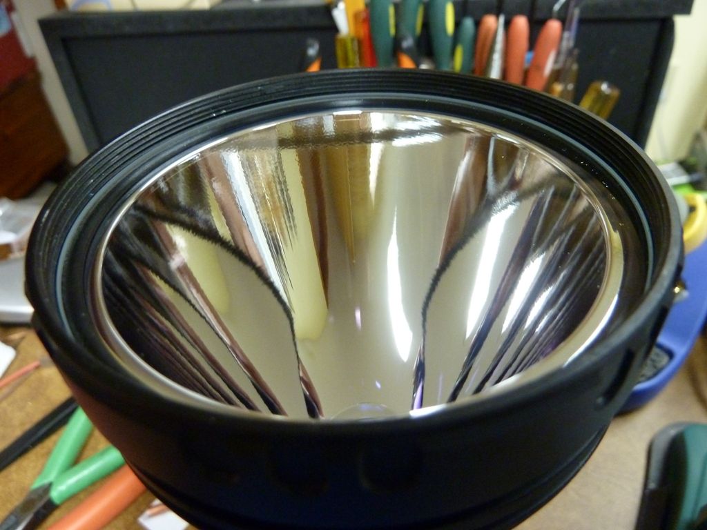
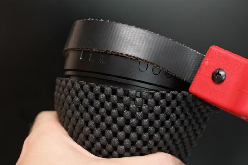
To ease some concerns, I got two K50's in this evening. So far the first one is coming apart pretty easy. The tail cap unscrews by hand and the bezel comes off fairly easy:
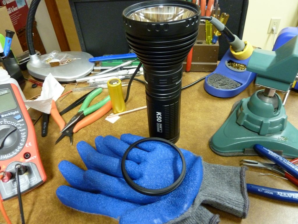
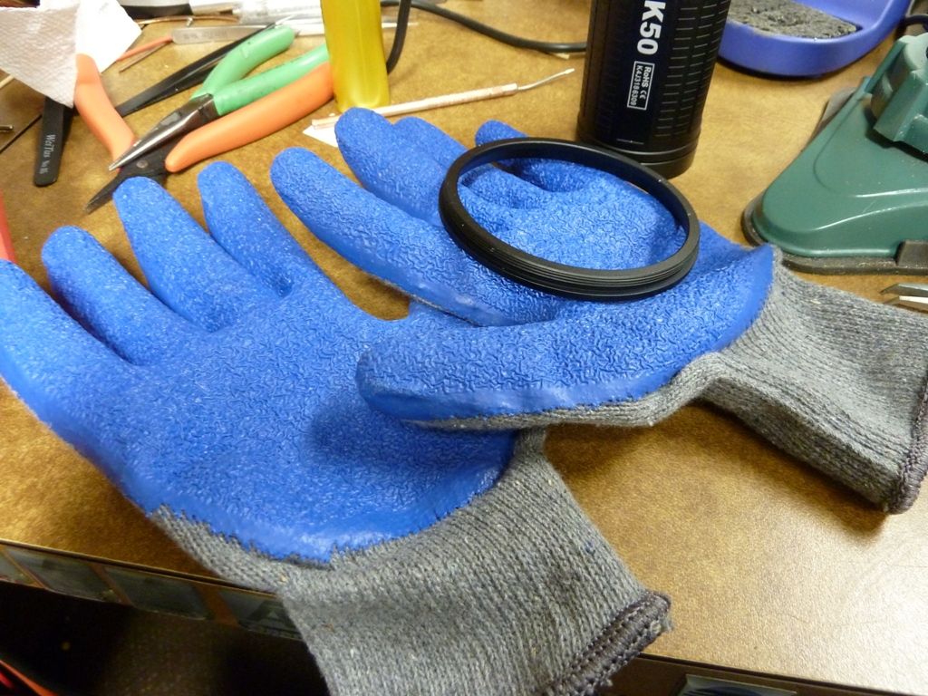
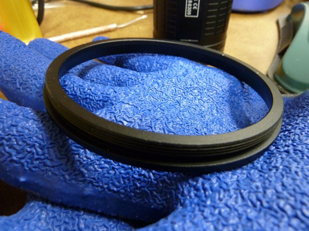
These sticky gloves were pretty cheap at Home Depot and worked great to loosen the bezel - its on pretty tight, but also clean of glue.
Don't mind the mess. Too many projects goin on right now...
Thanks for the pics Tom.
I’m currently out for a vacation with intermittent wifi so I’ll catch up later!
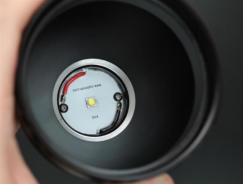
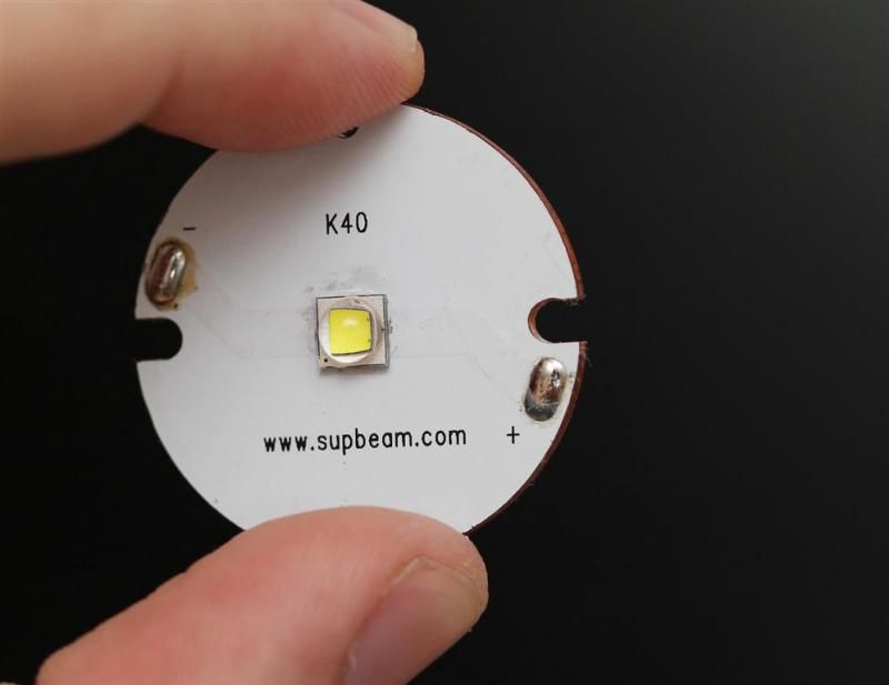
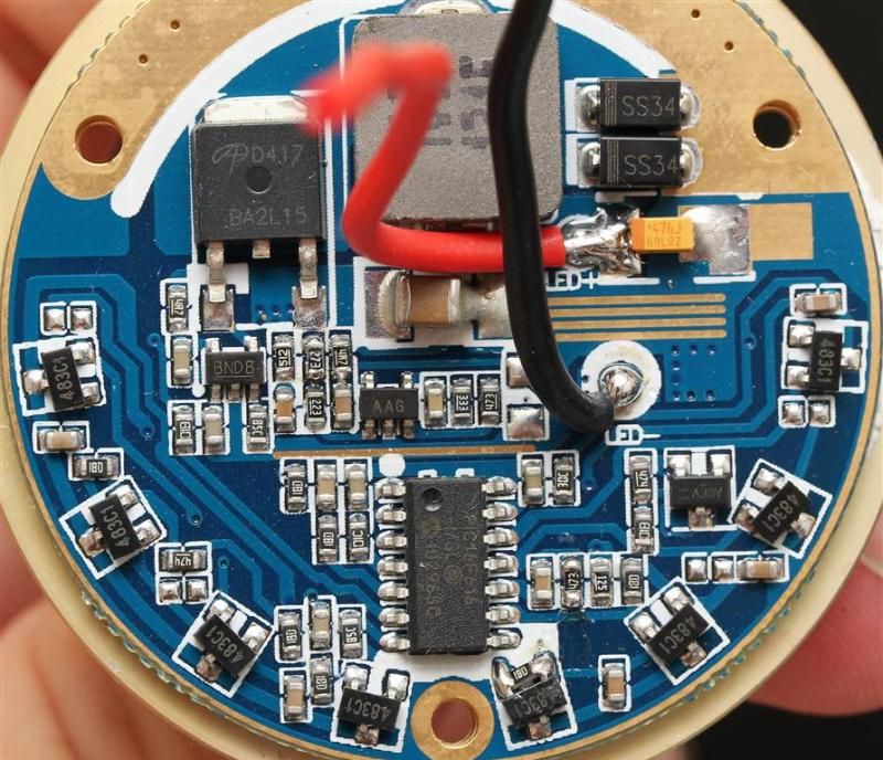
I accessed the driver - they use thermal epoxy on the area of the resistors, so you have to pry the cover off. I did it, cleaned up some - it's clearly a labeled K40 driver. I measured 1.7A at 16.4v at the carrier, so theoretical max of 6.4A to the LED but we know it doesn't get that much - lots of loss with this design. Think on a TN32 I'd measure like 10A equivalent to the LED, but measured only 5.5A - 6A at the LED.
Clearly though the resistor area has a stack of 3 resistors, top one is R120. But, there are other SMD components, 3 legs, looks almost like FET's. Also a fine wire/jumper is in this area -- have to be real careful in clearing the epoxy around that wire. These SMD's are not in a K40 or TN31 driver -- different for sure.
I measured lumens and throw - throw is a bit higher than others measured, actually I got over 200 kcd, but man, these things can really throw stock - checked outdoors too. On one K50, the lumens measured was almost dead on with the specs in all modes, but the other light was a bit higher. selfbuilt measured it much lower than the specs -- who knows...
So far, can't get the other threaded joint open - the one at the mag ring. It would make it easier getting that one open to work on the emitter area - I hate working down a big head. Didn't try the strap wrench's yet on it. I suppose next step is to wire up the LED neg. to test stock amps at the LED (no idea what that is), then pull off the stack of resistors and see what they are - doubt I'll get to this yet - maybe someone can beat me to it and post? 
Tom, was it easy to pry the driver of the the cover?
Just got my light in today. Did some measurements and most of the teardown. Probably wont do anything more today.
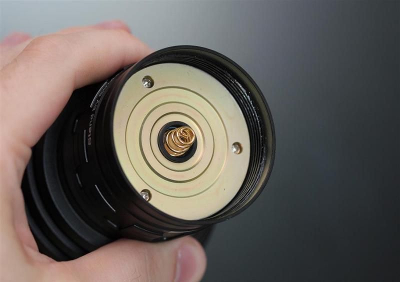
Held the head of the light in one hand (with some grip help) and a strap wrench in the other. On the picture the strap wrench is not properly in place since Im holding the camera and the flashlight.
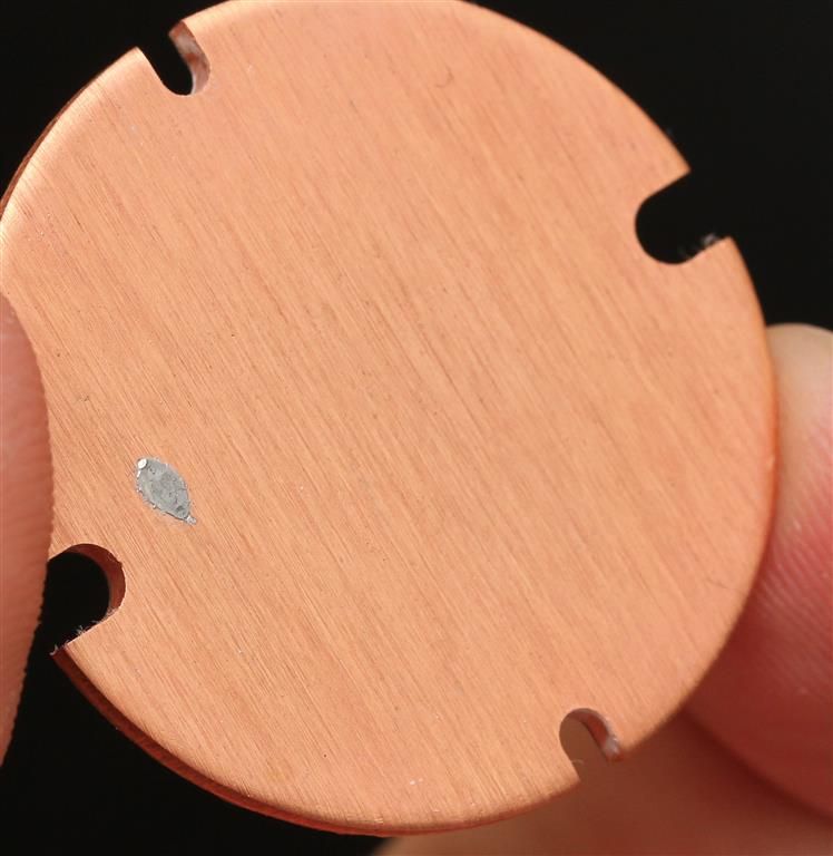
After cleaning. Mine had a little solder blob on it..
Top side of the driver.
Pill is about 2 mm thick.
Here are emitter amps from lowest to highest mode according to my cheap DMM.
Moon 0,00237 ( second time I measured 0,00245)
0,058
0,53
1,43
2,69
High starts at 5,03 and sinks to about 4,9A in a minute.
Basically 5A to the emitter.
187kcd (In comparison, I measured a stock TK61 to 181kcd with similar "correction increase". That light is driven with 2 amps less at the emitter.With a "stage 1 resistor mod" TK61 measured about 267kcd at 4,7A)
Measured about 1470lumen OTF. (Once again Ive added a bit to readings in order to get a bit closer to others on BLF. In comparison, a "stage 1" resistor modded TK61 showed 1533 at slightly lower amps)
Im still working on my correction numbers. Sometimes I used different values. Finding a balance between ANSI and the higher numbers typically posted on BLF is not easy.
RaceR, how much torque did you apply to get the head off? Thanks for the pics.