Supbeam K50 V2 Mod Thread

Wow - very useful info!! Shame it's a bit flaky at high amps. Not sure if we can find out if this is what others are/were seeing. vinh obviously has the most experience and his customers generally aren't that savvy to measure these things as precisely, or at all. I calculated the max throw is in the 640 kcd area, based on 7.0A-7.5A with perfect focusing, and funnny this is what vinh, I believe, reported. I've seen big variations in kcd measurements made at different distances by rdrfronty, so that must be taken into account.

I would think the TN32 would have the same issues since they seem to have the same K40/TN31 driver with the same "stock mod".

Excellent info. Thank you RaceR86.

Sounds like that "stock" mod is for the birds. In the end, it appears that the driver doesn't do much better than the unmodded driver (TN31, with resister bank shorted) other than for the first minute. I rather have more stable output.

Vinh`s (latest??) K50 is specified to run in the 6-7A range. With the behavior I have seen Im not surprised to see that he is specifying that range, and not a specific number.

If he have just done a resistor mod, im guessing the light is mostly likely doing up towards 7,5A at startup and sinking below 7A before the power decrease (mine is 6,9, or more like 6,6-6,2A depending on how you look at it).

Use ANSI calibrated measuring device, and measure at 1min 15 sec instead of 30 seconds and there will not be that much difference between the different resistor mods that started in the 6,2-7,5A range. Certainly not anything visually.

Im quite confident that Im running a reliable setup. 20 minute runtime test. Extremely hot light, uncomfortable to hold. No issues.


ImA4Wheelr, I certainly got an amp increase out of it after the 1 min 10 second mark too. But not as much as I had hoped for. My lumen and kcd numbers would have been better with an XM-L2 U2 1A. I cant tell how it compares to the K40 /typical TN drivers when modded. Never owned one of those lights to see how they behave once they are modded.

I can add Im getting same output numbers when cells are 3,7 as when they are 4,2. So that is a good thing.

Oh, I wasn't referring to your mod. Yes, you certainly increased the current before and after the step down. I like your mod.

I just meant that compared to the older driver in the TN31, the current increase isn't enough for me to have to tolerate a less stable output situation.

EDIT: next time I'm in my TN31, I will need to check for this step down you discovered. I didn't measure current for that long when I was working on it.

Is the TN31 dead stable on the output?

Maybe RMM`s latest trick for the HX-1175B will work on the K50?

Ive got a suitable part, but Ill leave the K50 as it is for now. Got some other interesting projects.. ^^

Tom E is probably a better judge of that as I think he has done x number of TN31's.

My one TN31 seemed to give me an oscillating type reading, but it centered around some where under 6 amps. It didn't drop while testing. I didn't measure current long enough to know if it stepped down at 1min10secs.

Can a sink be added to the FET’s? Would that help with that falling amperage issue?

I do like the idea of a beefy aluminum reflector. I like to file a bevel to the base so that it’s narrow around the emitter, giving clearance to the wires. I have that same big Noctigon on the way, is the central pad linked to lead pads towards the outer edge or just exactly where are those?

Thanks a bunch for those results and the various testing, spot on with what we are looking to know! :slight_smile:

Not sure if I understand the Noctigon XP32 question.

You can pretty much see all traces and everything here:

Edit:

I might have some issues with my light. Not sure what, but ive damaged the stock carrier springs. Was doing tests with low voltage batteries (3,3V) Same issues with improved springs... Light works nicely with cells with higher voltage. Too tired to do more testing today...

Light perform nicely outdoors. Beam was just as expected based on beamshots I have seen.

Thanks for the work so far, RaceR86.

My K50 arrived today (from HKE, as I missed out on the GB). Ordered on the evening of the 17th, delivered today, 29th. Not bad for standard shipping to AU.

Initial thoughts/observations;

Came with the full kit, same as in the GB, warranty card, etc., & also an AU mains adapter thrown in.

The adjusting ring does have a slight color mismatch. Of course, this was the first thing I looked for, with all the hoo-ha going on. I had to look hard to see the difference, & I probably would not have noticed if it hadn't been a hot subject atm.

Battery carrier is really set up for protected/long cells - my laptop pulls with solder-blob on top were a fairly loose fit.

Stock performance is pretty impressive (which you would expect from a high-end light).

The reflector seems to have a extremely light OP finish, definitely not mirror-smooth.

Overall, I'm pleased - this is the most expensive light I've purchased.

Unless I'm mistaken, there's no reason to fit the Noctigon XP32, unless you want to change to XP-G2 (or XP-L), as the stock plate is direct-to-copper.

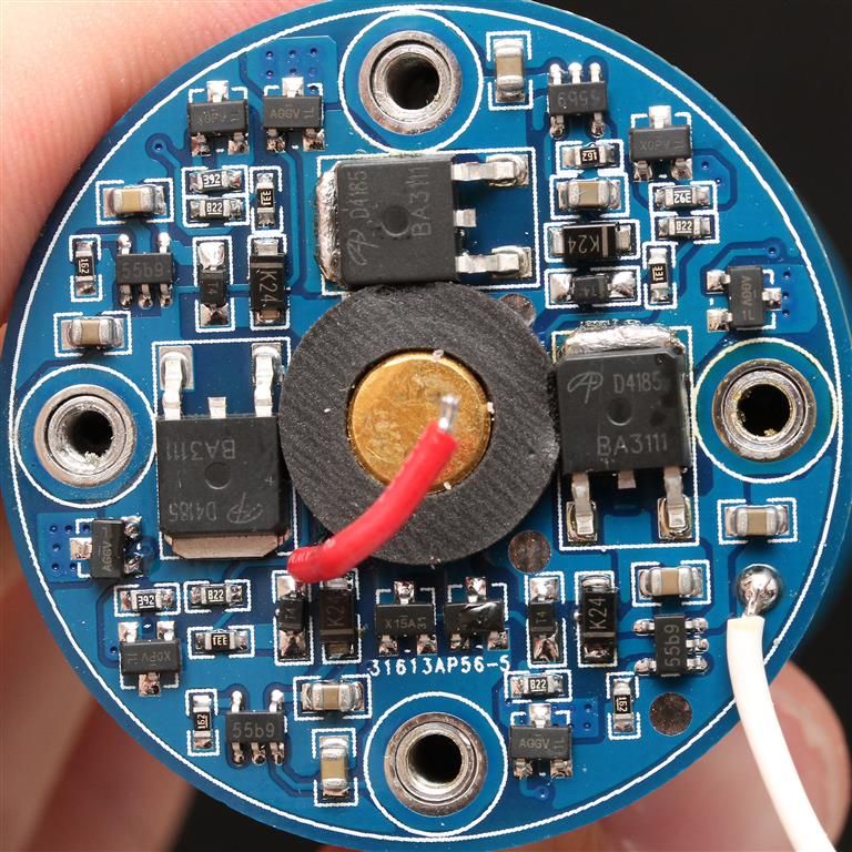
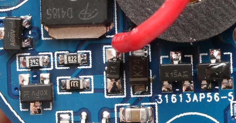
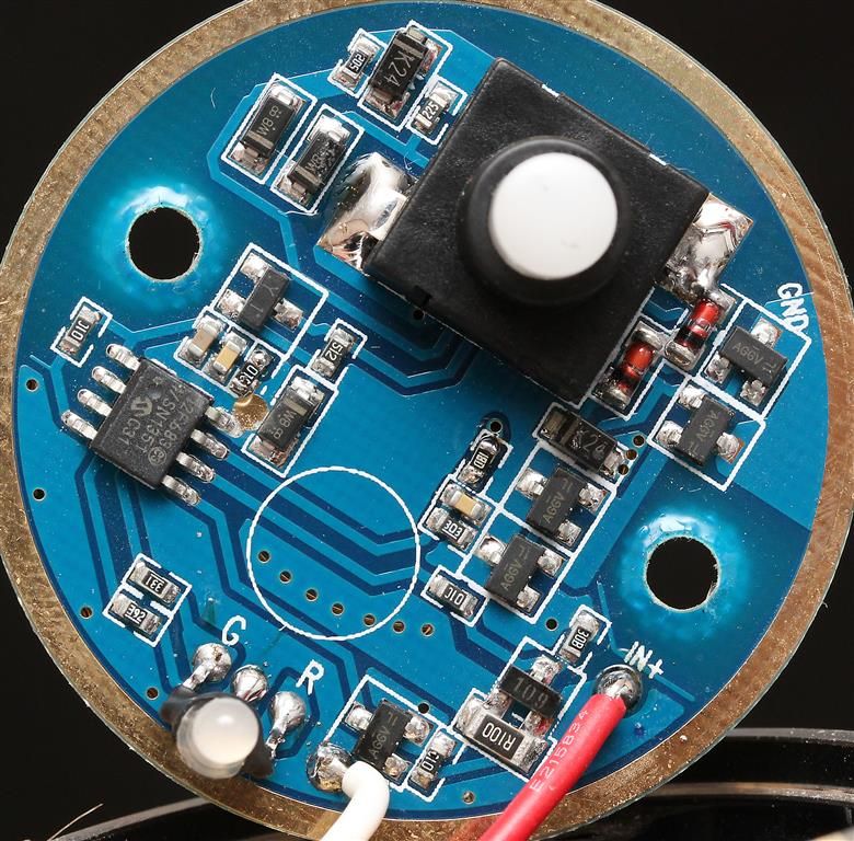
I think I'll run with a de-domed XM-L2, as it's a pretty tight spot already, & amp-boost. I'm eagerly awaiting for more info on the driver, to see if that initial sag can be overcome. :beer:

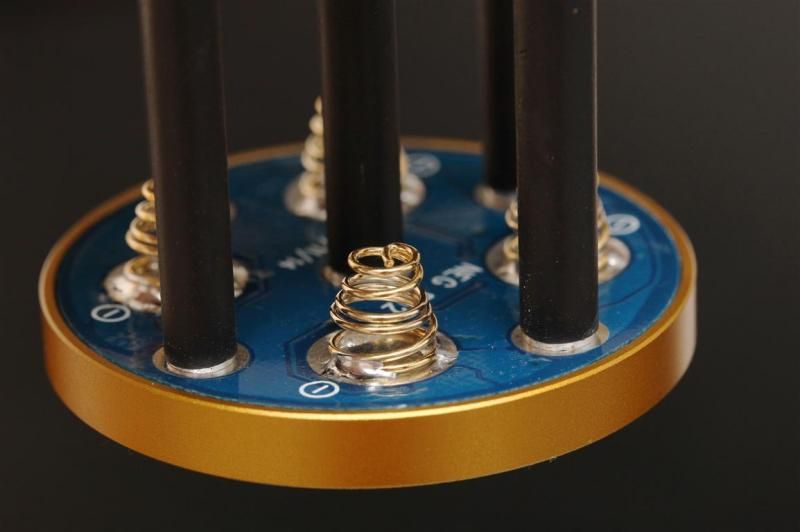
-edit - also, how do you find the spring arrangement in the tail of the light - seems a little convoluted to me... plenty of springs to have to resistance-mod in there...

-edit #2 - Stock throw reading taken @ ~10m; right on 200kcd. (~894 meters).

somebody try replace with one xpg2 ?

FmC. I believe negative goes out the center spring at the back of the battery carrier. The other two springs are used for other stuff. There is a lot of electronics in the battery carrier, and some in the tail. Its beyond me. Ill post pictures tomorrow.

Im not sure the battery carrier is up for the amps that you get on a modded light when its running with low voltage cells.

May not be smart to mod the light... Not because of the driver, but because of the electronics in the battery carrier.

Can someone check on the stock light if the bottom of battery carrier becomes hot of you use some (panasonic) cells at around 3,3V on max setting for a minute or two?

I can test with Samsung ICR18650-28A’s unprotected. Won’t be until about this time tomorrow, though.

Ok - I decided to stay up & have a few :beer: ’s , & discharged some of my Samsung ICR18650-28A’s down to 3.30 - 3.34v.

Tested in the K50 for a little over 2 mins on high.

Externally, no noticeable difference in heat.

Took the carrier out, & noted that the end was slightly warm. Not hot. But warmer than the rest of the carrier.

I had to put it up to my cheek to get a better idea of the temp difference, as my fingers are pretty heat-tolerant due to my work.

The battery indicator light was flashing red when I started the test, & I noticed that it had gone out completely when I switched it off.

Thanks FmC. That is nice to know. Cheers mate!

My full update below:


Ive had no issues with the driver. With my resistor mod, input amps is 2,7A @ 12V and 2,9A @11V (11v divided on 4 cells means 2,75v on on load) when tested with a powersupply (should roughly give efficiency around 80% or a bit lower). I did not think up towards 3A should be an issue for the springs in the carrier.. Yet, when I did some startups with some unprotected NCR18650PF cells at around 3,3V there were some issues. It started with full output, but very quickly showed some strange behavior with the output. I took out the carrier and the bottom of it was burning hot.

Springs had "sagged" a bit. Typical issue if they are seeing too many amps.

I replaced the springs and added some 22awg wire too them. Tested again. Battery carrier got really hot in a short time.

Top of the carrier is easy to disassemble. Nothing to see there. The bottom end is not supposed to be opened. I used a hot air gun on the stuff that was inside the screws in order to screw them out. Here is the battery carrier bottom side.

Notice component at the far right. Not sure about the component at the far left.

Here is a picture of the electronics in the tail:

Not sure what do do know. Sup/Acebeam can sell me a new carrier. Price is not bad considering all the components on it. (20$ + a little bit in shipping)

Im considering to just get a new carrier instead of trying to replace parts in mine that may be broken or damaged. And then just mod the driver back to stock....

My light works nicely otherwise. Ive been using it outdoors a bit the last two nights. Taking it for a walk and comparing with other lights. But im not a fan of a light that seems to have issues with low voltage cells. Im not a fan of using the built in charging system when Ive got some components that look like they do.

I wonder if the electronics in the battery carrier is not up for the task of increased amps when cells get low, which naturally increases amps more in a regulated light like this.

Electronics gurus, feel free to share some insight and knowledge.

Wow, that a lot of crap in there for a feature I'll never use (in-light charging).

Wow, lots of stuff in there. Seems like we are going to need a OSH Park DIY alternative carrier for this light. Wonder why they didn't go 2P2S on this light. Would have simplified the design a good bit.

Wires on the tail PCB go to the charging port, right? What do the wires on the carrier PCB go to?

Yupp. Wires on the tail go to the charging port.

On the carrier:

Center contact path is seen in the picture.

Red wire on the carrier goes to the middle contact path.

White wire goes to the contact path closest to the edge.

OK, so I will pose the question and see what all you gurus maniacs out there can do.

Can the stock driver be modified to handle the voltage for an MT-G2? I figure the MCU/controller might have to be "protected" by some type of bleed like a zener, but.... Is this a FET based driver? If so, can the circuit be manipulated to use 7135 chips for regulation and get rid of the fet?

In other words, I want an MT-G2 at 9 amps, (never gonna get 9, but...) and do it with regulation instead of DD on high. AND I want to continue to use the normal magnetic ring for modes, so that whole part of the driver has to remain the same.

Anyone???

Everyone???

I don't have a light yet, don't know where it is, but it should come if they didn't stop the shipment, LOL.

maybe 6x18350 S/P for the batteries - Better back off to about 5 amps then. EDIT: Sorry, thought it was 3 cells, not 4. Series? What is all that crap in the carrier? Just for recharging?

Stock carrier is 4S, or 16.8-12v. Driver is a buck driver, but if other reports are correct some component on the board (the buck controller) has an output voltage limit, and cannot adjust voltage up high enough to run a MTG2. It would take an extraordinary amount of luck to find a pin-compatible controller, like something in the same series from the same manufacturer, that had a higher output voltage limit. Otherwise, I don't know of any way to keep the magnetic control part.