Never heard of anyone injuring themselves while removing a flashlight bezel. Must be seriously tight!
ToyKeeper found that a carpeted floor can be a big help. Push the light bezel first into the carpet and twist.
I have a section of 1/2” thick floor cushion, the stuff they put at a work station to stand on. Kind of a foamy rubber. I use that to press the light into and grip the bezel, works quite well.
I used the back of a mouse pad for traction, but all I could see it doing was ruin the mousepad. I don’t have any carpets around here, but maybe I can find an ESD rubber mat.
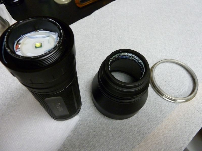
I seriously thought the bezel was glued, but looking at the reports here it was just tight, very tight.
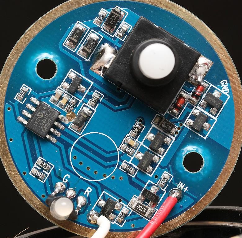
I used a dab of hot glue to fill the void between the rubber boot and the clicky switch. I didn’t like the mushy feeling, so now the switch has a very solid firm feel.
RaceR86’s photo:
Has anyone been able to access the mode selector switch? I would like to disassemble it and add some lube and maybe reduce the clickiness of it. I prefer the tougher ring with subtler indents like in the K40.
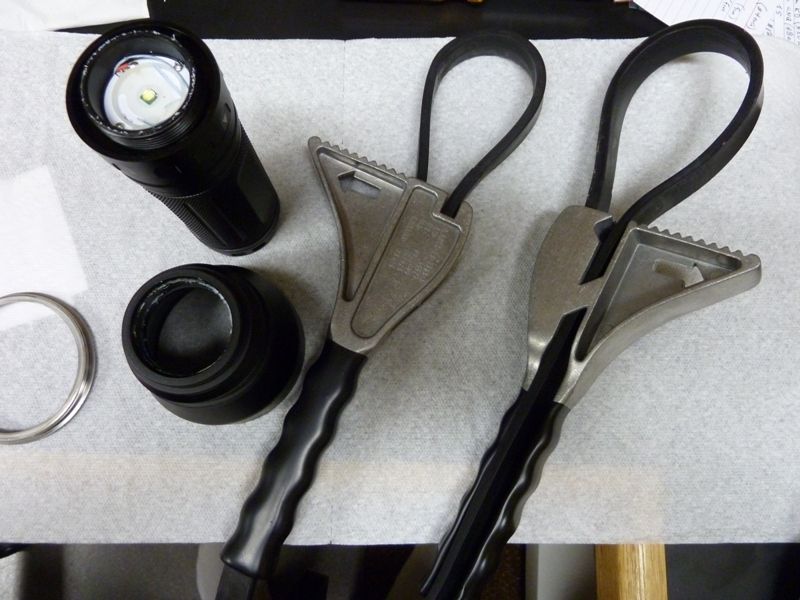
Ryan - you mean the mag ring? I tried with strap wrench's - No Go. She is sure glued tight shut. So much for no glue -- I've gotten that threaded joint open on TN31's and it takes quite an effort, usually. They use a pretty good LockTite.
I would like to open for two reasons:
lube it up with Nyogel as I've done before - definite improvement
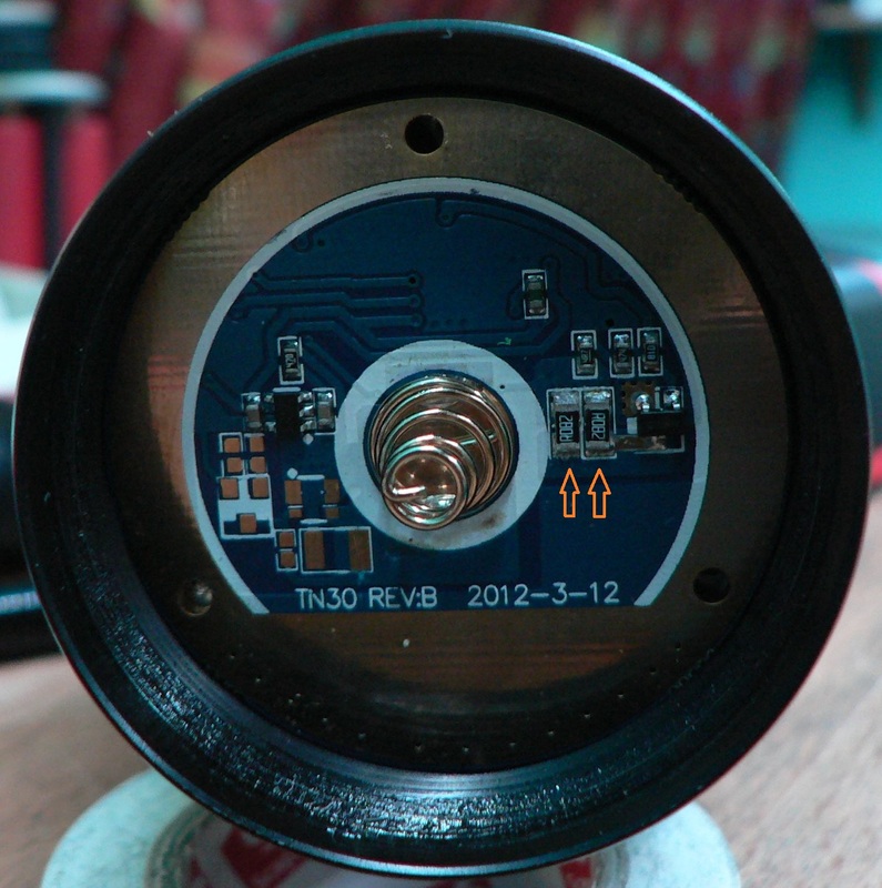
Yup, the mode selector ring. I remember noticing two bumps which looked like the ends of two screws looking inside the driver compartment.
I’m not sure if the screws are from the MCPCB, as the screws that hold it down are fairly short. I wonder if this indicates the threads are fastened by the two screws instead of loctite.
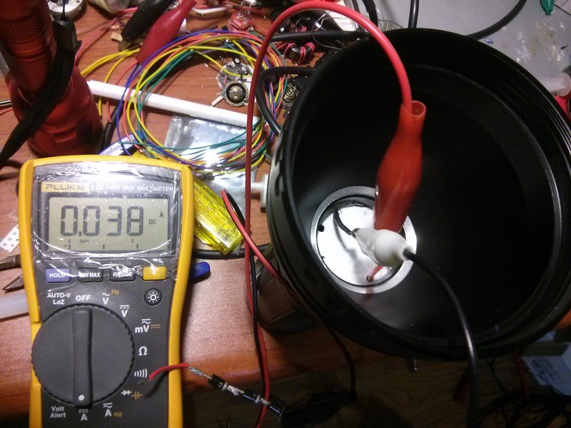
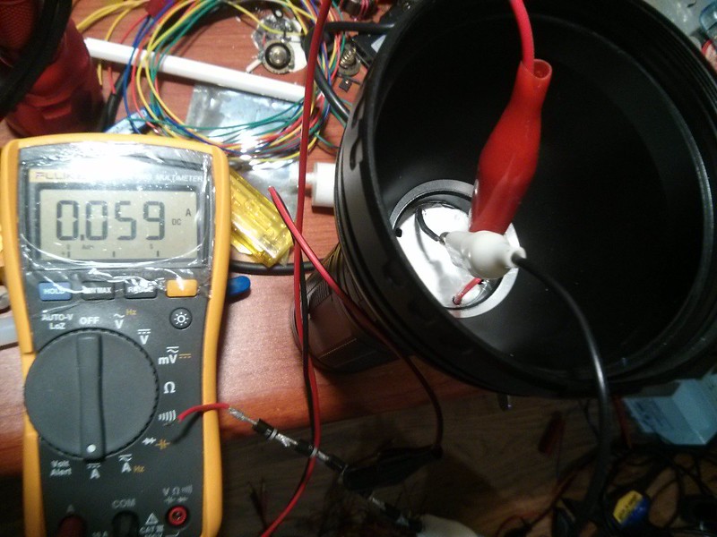
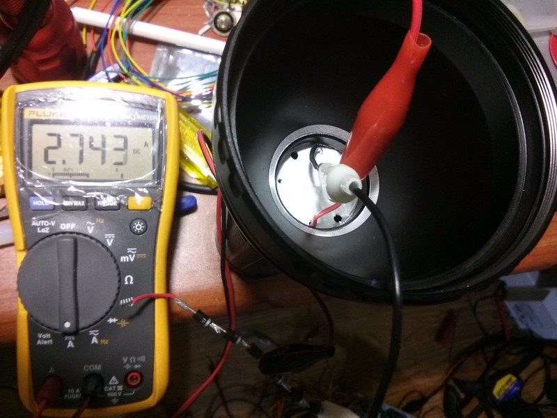
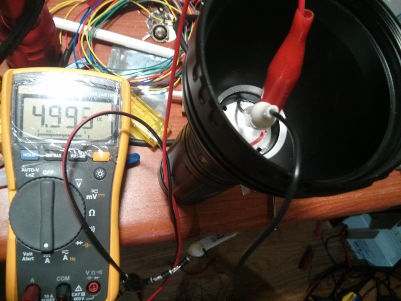
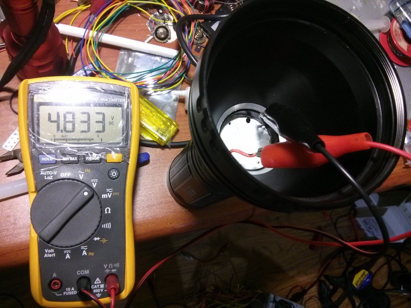
EDIT: We gotta figure out if there are any way to adjust the voltage and also why the current drops like that. Was you emitter in the test well heat sinked?
Figuring out how to control the max output voltage would be great for MT-G2 LED’s. I’ve contacted Supbeam many times about selling TN30 (3x XM-L2) boards, but they wouldn’t budge. Maybe a 50 unit GB would work?
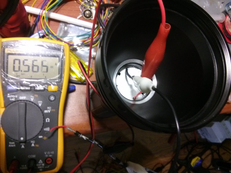
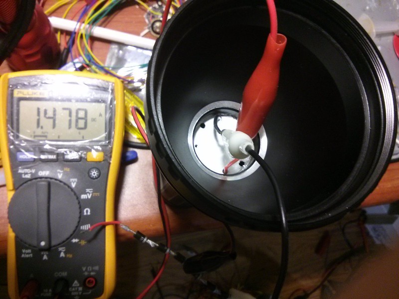
The current drop is probably due to the driver itself overheating and individual components not being able to handle the heat. My guess is that as the sense resistors heat up, their resistance increases and the output current decreases, which is probably why Supbeam put a blob of thermal glue between the driver cap and the resistors.
I was using 1N4007 diodes I use for general purpose testing. I had three of them in series, which emulates the forward voltage of the XM-L2 LED.
I haven't seen a single picture of the TN30 driver. You seem to be the only person that has worked on them. If you have one out of a light, it would be great to see a front and back picture of it.