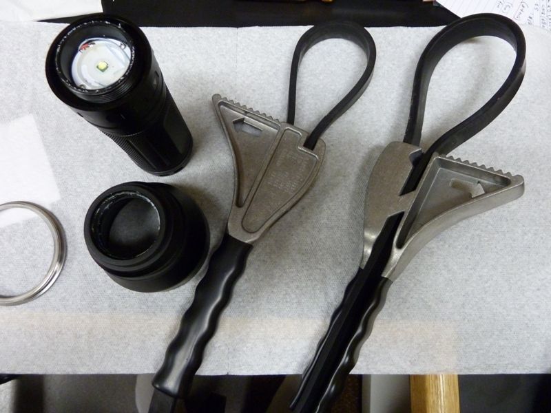
Ryan - you mean the mag ring? I tried with strap wrench's - No Go. She is sure glued tight shut. So much for no glue -- I've gotten that threaded joint open on TN31's and it takes quite an effort, usually. They use a pretty good LockTite.
I would like to open for two reasons:
lube it up with Nyogel as I've done before - definite improvement
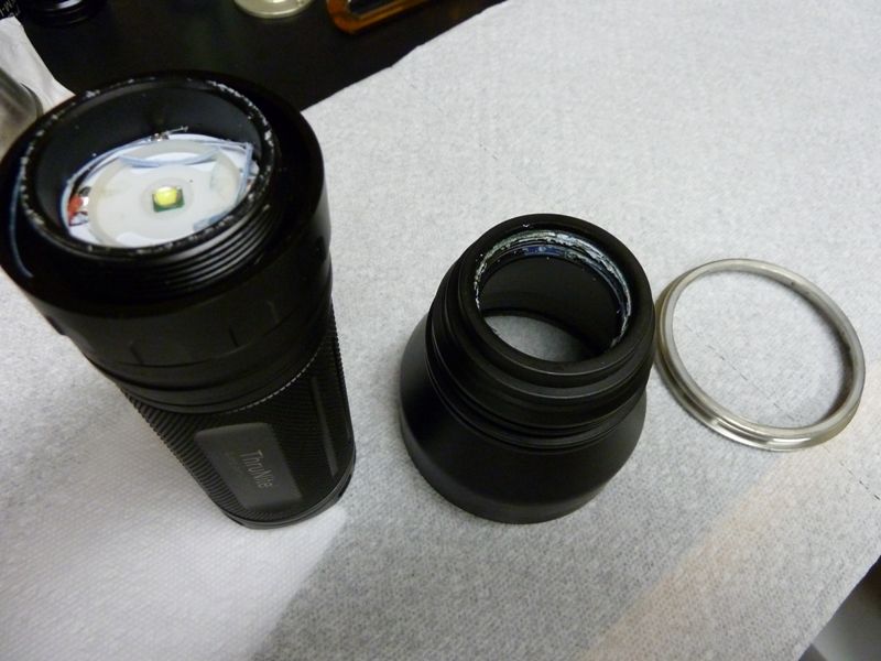
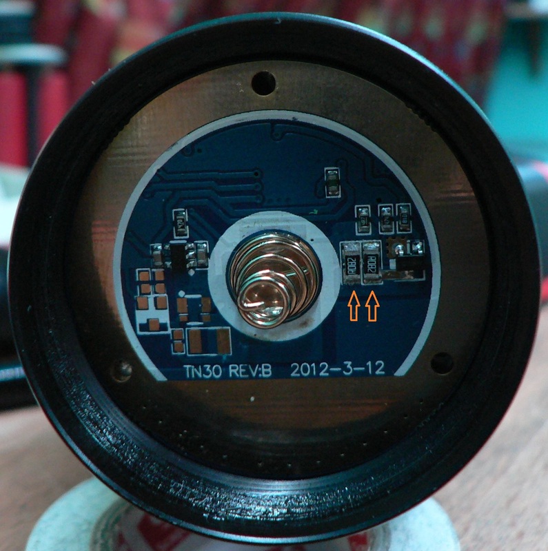
Yup, the mode selector ring. I remember noticing two bumps which looked like the ends of two screws looking inside the driver compartment.
I’m not sure if the screws are from the MCPCB, as the screws that hold it down are fairly short. I wonder if this indicates the threads are fastened by the two screws instead of loctite.
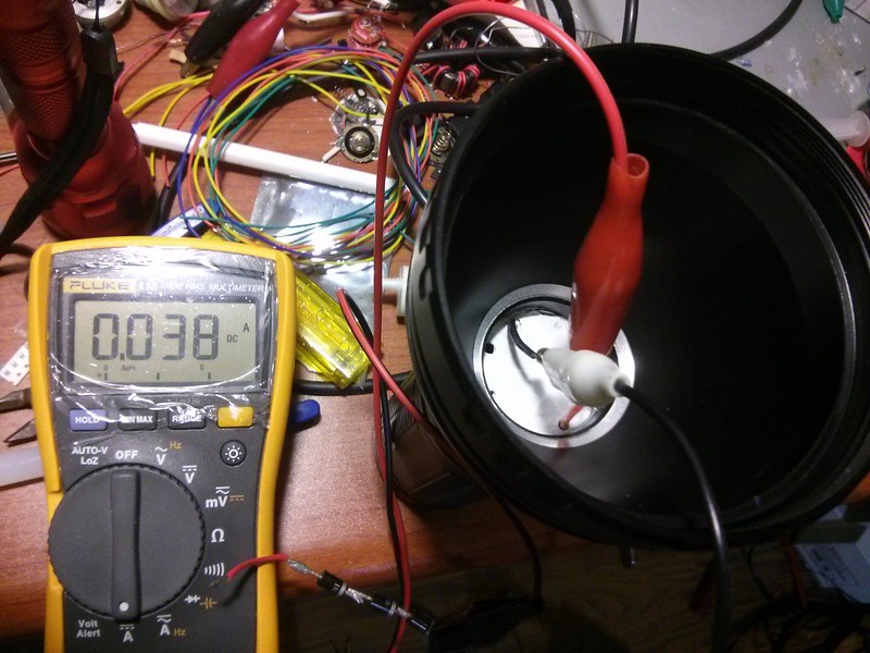
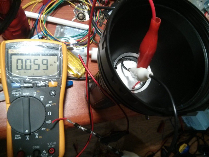
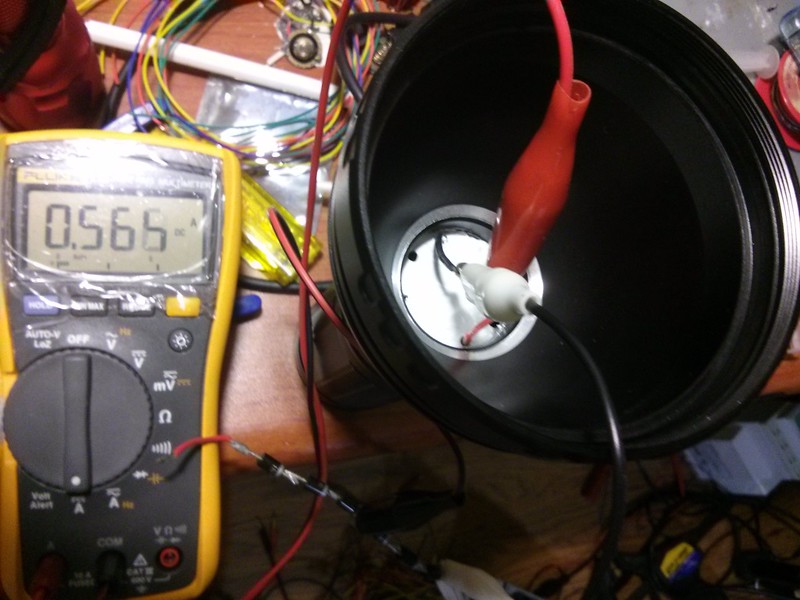
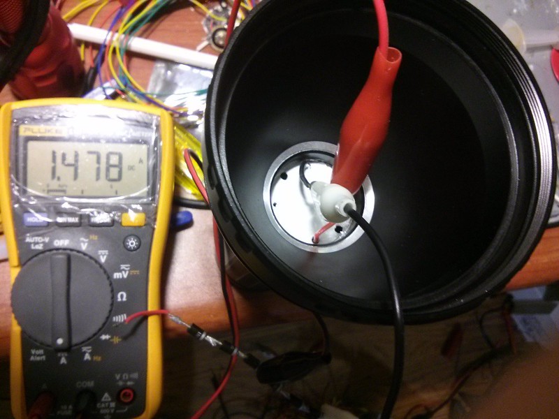
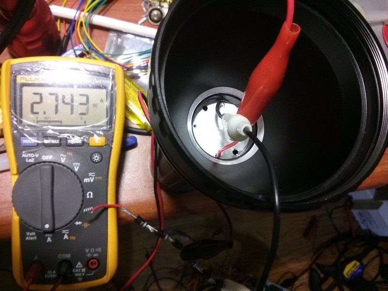
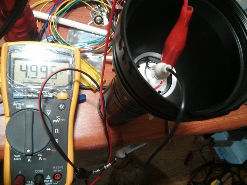
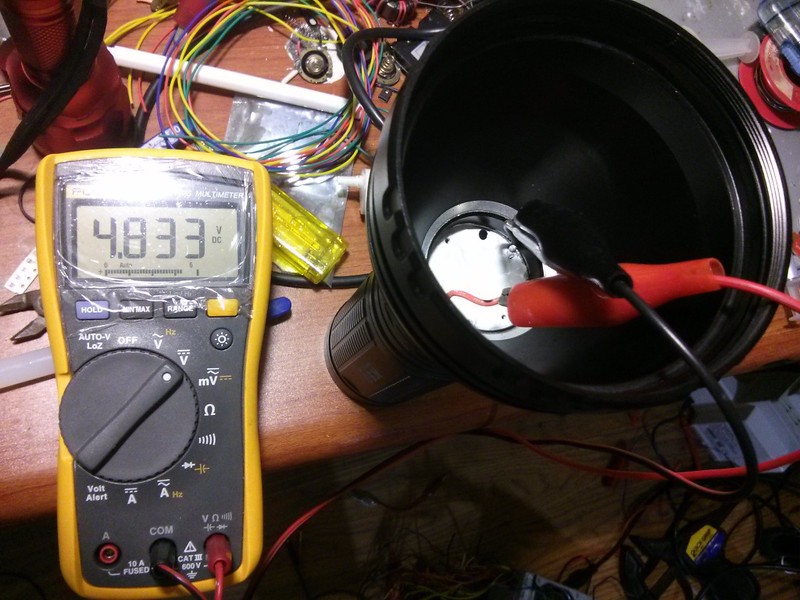
EDIT: We gotta figure out if there are any way to adjust the voltage and also why the current drops like that. Was you emitter in the test well heat sinked?
Figuring out how to control the max output voltage would be great for MT-G2 LED’s. I’ve contacted Supbeam many times about selling TN30 (3x XM-L2) boards, but they wouldn’t budge. Maybe a 50 unit GB would work?
The current drop is probably due to the driver itself overheating and individual components not being able to handle the heat. My guess is that as the sense resistors heat up, their resistance increases and the output current decreases, which is probably why Supbeam put a blob of thermal glue between the driver cap and the resistors.
I was using 1N4007 diodes I use for general purpose testing. I had three of them in series, which emulates the forward voltage of the XM-L2 LED.
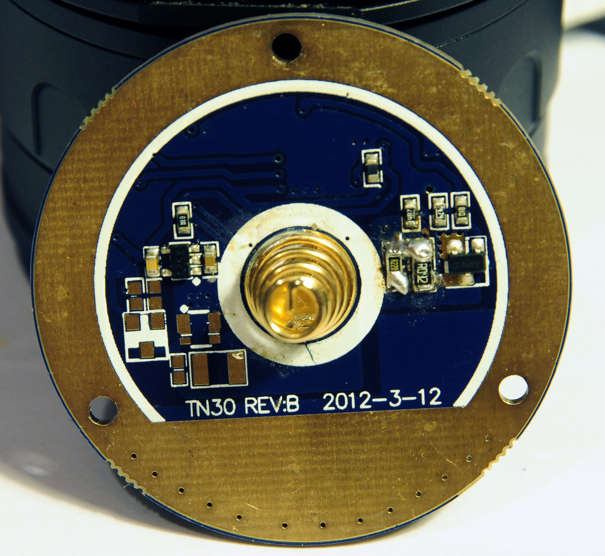
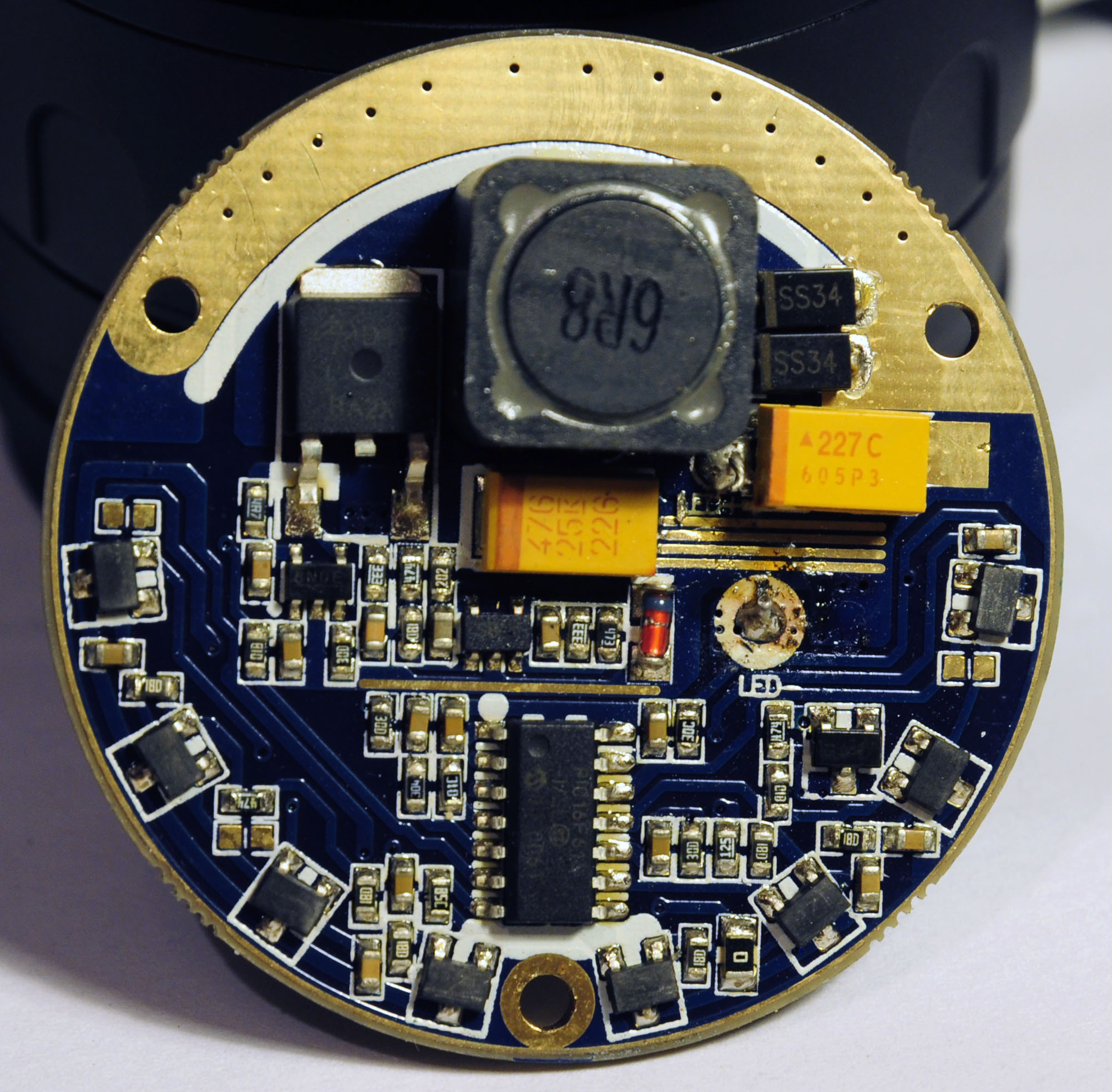
I haven't seen a single picture of the TN30 driver. You seem to be the only person that has worked on them. If you have one out of a light, it would be great to see a front and back picture of it.
I was about to update my 1st reply with some measurements but I decided not to because it would bother you. I couldn’t delete the post either because it would mess up the table of contents so I decided to abandon it. No offense intended, I was just playing around.
So put the updates in the first post, not the first reply, and nothing gets messed up. What's the fascination with putting the updates in the first reply, anyway? How is that any less effective than putting it in the OP? If you want everybody alerted, make a new post at the end of the thread where the new stuff is supposed to go anyway, saying "updated info in OP" or whatever, then a round of notifications go out, people see the new post at the end, and then go back and look at the OP. It works just fine like that on every other forum on the planet.
Thanks again ryansoh3. I guess I have seen images of that side of the driver. Even in this thread at Post 154. Just didn't realize it. Looks exactly the same as far as I can tell.
Look forward to seeing the other side. Maybe it will help us with this driver. Thank you again.
Here are some shots of the driver. I couldn’t find my lens extension tube, so the quality isn’t too great. :~
They are very high res, so click on the link for fullscreen+ sizes.