Yup…gonna have to do some revision…the cap doesn’t have a passthru to the + plane of the board…doh, can easily scrape the edge of the mask right below the C1 silkscreen to raw copper and solder a jumper
Might even rotate the chip like you did on your board wight…to cut down on the trace length
I am really digging the look of the board with the large polygon pour though, will be fixing…
wight, do you or anyone else know how to remove the white silk screening of the component on the copper pads under the tStop layer? I want it to print the outline of the IC but not print over the copper, I can gently scrape it, but would rather not have to
Um…yes they do (at least they did on this run (was the 5 day expedite test)
It’s a crappy pic…but the white outline and little feet of the 6 pin IC is printed over the top of the pads, heck they even printed the outline of the USB housing over the bare copper of the VIA, everything else is spot on
I even scraped one to ensure…sure enough raw copper under the white paint
wight, I found a better way, bridge the capacitor, solder the cap from the end pad to the ground pin on the USB A pin
I might just trash these and get another set after I do the fixes
There were errors on those boards anyway…my mistake, won’t get them to remake them
Besides I believe I fixed my screwup
Even shaved a little bit off, and removed the more or less useless LED and resistor
2 layer board of 0.87x1.5 inches (22x38mm). $6.50 for three
Wight, and/or others…wanna check it out please
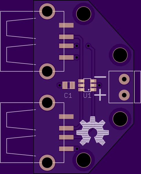
Render
Top
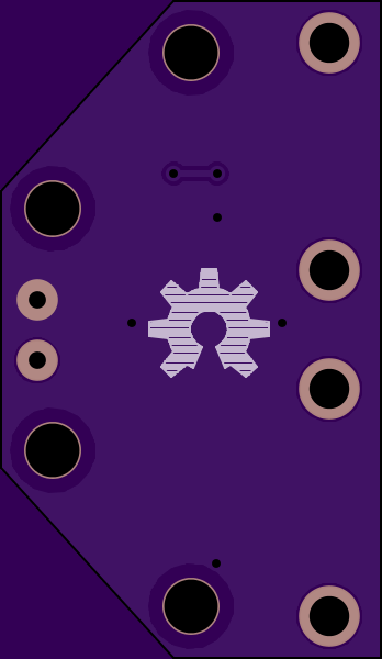
Bottom
A little 3D
Files
Oh and Halo… I sent them OSHPark an email…this production was under the Super Swift Service “test” they might have skipped that step in the rush…but thanks for the heads up on the producers removing the mask, Thanks!
um…duh…click the thermal outline, properties…actually had to turn off thermals for the pads to be solid instead of the broken pattern
Thanks Halo…
Do you guys want the “status led”?
More or less going to be on all the time the board has 5vdc applied to it
Files updated with thermals off (no render, same as the above, just now instead of having to draw a trace over the thermal cutout area and having to name it, it removes the auto gap created by the thermal parameter)
Halo… is correct. Note that I’ve got thermals turned on and nothing “covered” in all the pictures I posted on page 2 (you may need to zoom in to see the thermals).
Make sure you’ve got your polygon named correctly (same net as the stuff you want hooked up to).
It’s weird, I unchecked the thermals on my Eagle (they were on originally, they are off now on the new design) and the spaces went away on the redraw with ratsnest, with the thermals on, the little gaps were there
I had used a “cheat” method and used a large wire and named it the name of the polygon pour to cover up the thermals…removed them too
You can squeeze the board size smaller if you leave the led off.
I see you already have the led placed between the ports so it wouldn’t save much space leaving it off. You culd leave it on and people always have the option to just not populate the led/resistor.
I don’t actually plan to build or use one of these, so the status LED is of no consequence to me. I’d throw in the kitchen sink if there was space on the PCB. Earlier I added a second status LED, just for flexibility of placement.