If the board in the tailcap is stripped/jumpered the charging port won't be connected to anything any more.
The charging cord could be used to hold this years school picture of the kiddo on the fridge. ![]()
Ok, so I dedomed the LED, braided the springs and upgraded the driver -> LED wires and it all works fine except it won’t turn off!
All the modes work correctly etc but it won’t shut off via the tailcap switch, only if I turn it to standby. Any ideas what could cause this?!
Something has shorted with your braided springs?
Actually I see there is no need to use copper braid on these springs. Assuming it is 6A through the LED each spring in the battery carrier will only see about 1.5A.
I just braid the springs on most of my lights just out of habit now whether they really need it or not.
I assumed there must have been a short somewhere. I have doubled checked all the springs and there is no shorts anywhere. I only use 1.5mm braid and I run it down the middle of the spring so it doesn’t touch anything else. In the tail cap I only did the centre spring not the outside ones.
Check continuity in the tailcap to see if the current breaks when you click the tail cap. perhaps your bypass is working correctly but the heat you used melted the switch?
Edit: Also sounds like what happens when the small spring inside the switch overheats. It won’t press the switch components apart to turn off or break the connection.
I will check that out. The weird thing is clicking the switch still turns the battery indicator light in the tail on and off. That makes me think the switch is still operating correctly?
Check to make sure the tail cap isn’t somehow contacting the back end of the carrier or otherwise bypassing the switch. That’ll do what you’re describing as well.
I have tested it by unscrewing the tailcap completely and just pushing it on until the springs make contact with the carrier and it still switches on. This really has me baffled, I have done the same mods to two K40s, TN31, TN30 and a TN35 and have never had an issue. I wish they hadn’t introduced this in light charging system and had just left it as a normal tailcap switch without all the other circuitry.
Also, how are you all focusing the emitter? I need the emitter to sit further into the reflector because there is like 3 distinct segments to the beam at the moment. The hotspot, a small bright ring around that and then the spill. I have taken the centering ring off but the reflector still won’t sit closer…
Will try and get a photo to show what I mean with the beam.
Hey guys, back again…
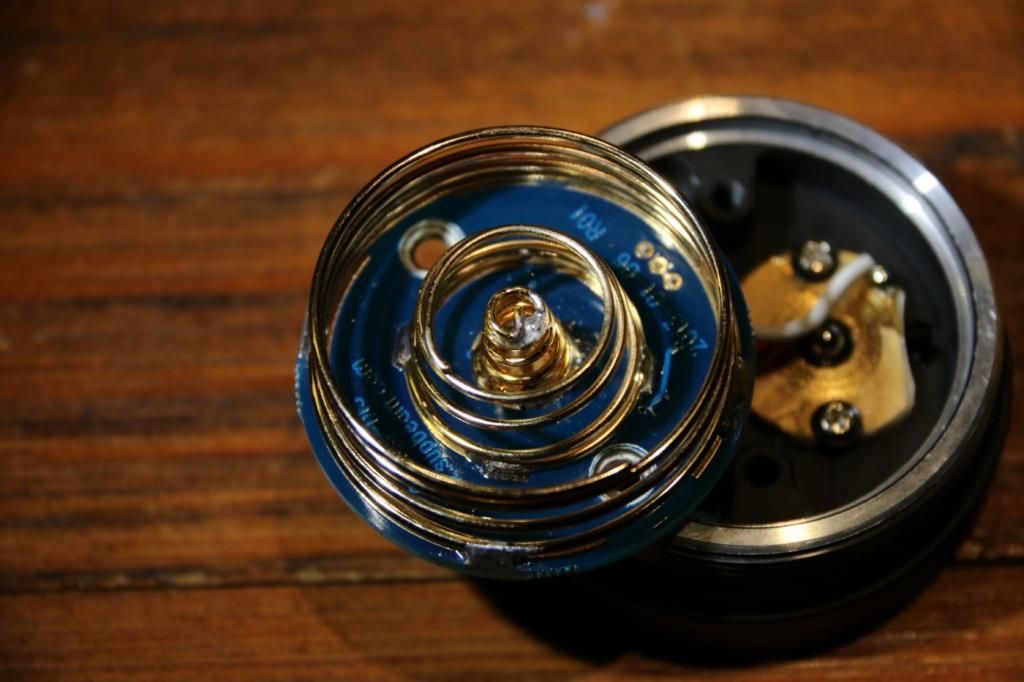
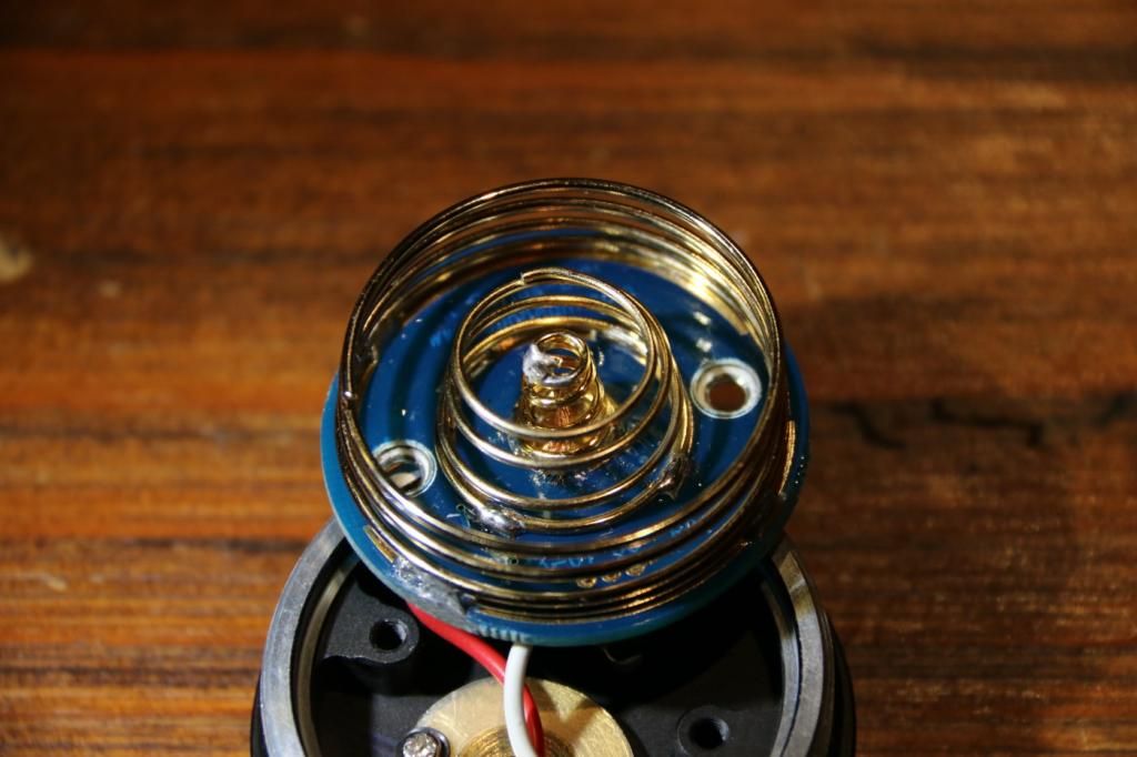
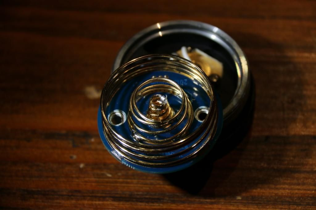
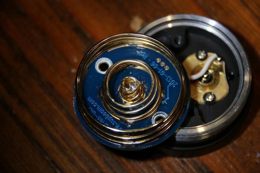
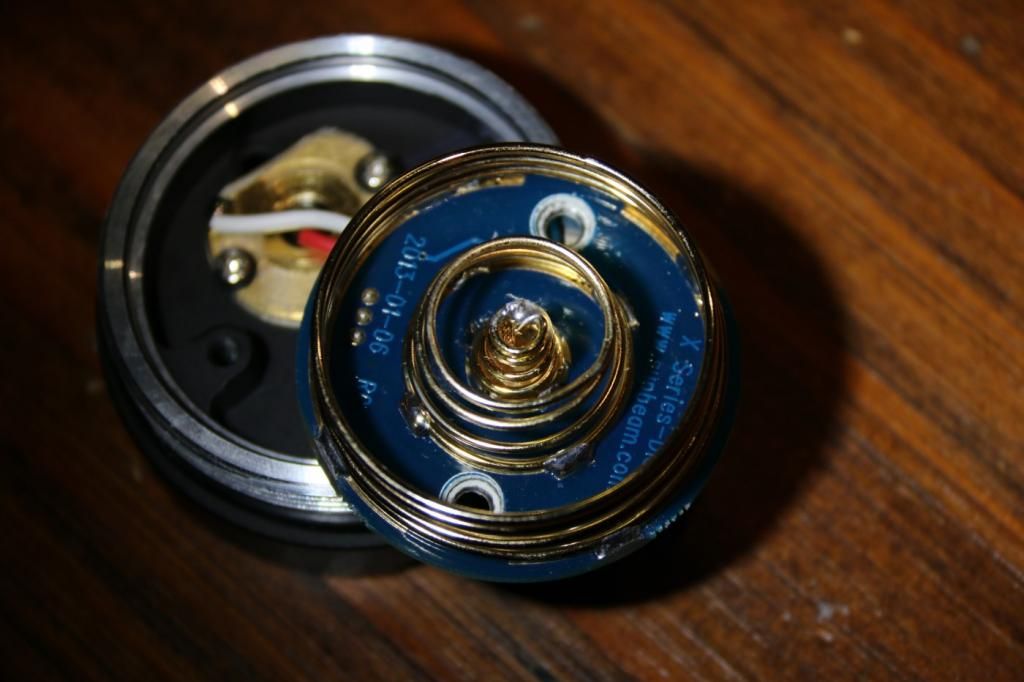
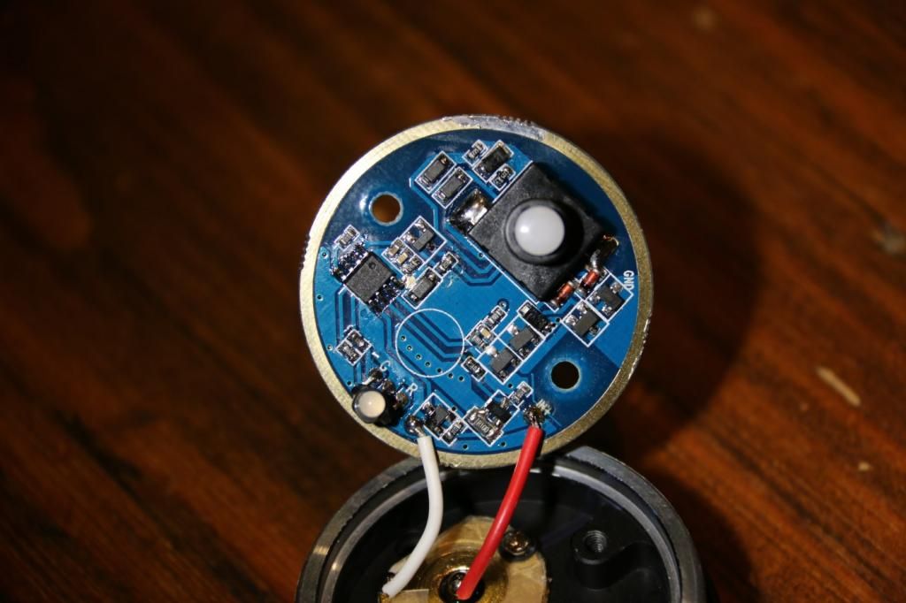
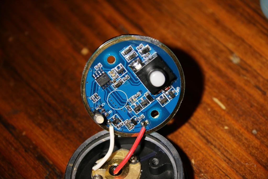
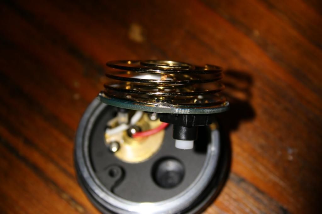
I’m really hoping someone might know what is going on here. I have been looking at this switch for two days now and can’t figure it out and I’m just baffled as to what is happening. The switch works perfectly, tested continuity across it and all works fine plus the led indicator on the tail works with the switch, I have looked for any sign of a short anywhere and can’t see anything, I even lightly filed down the spots of solder on the outer spring to ensure they couldn’t come in contact with the body. I have tested it by using some leads with alligator clips with the switch outside the light and it still won’t turn off so it is definitely something in the switch board itself. I have taken a whole bunch of pictures from different angles in the hope that someone notices something that I haven’t… Lastly when I was soldering I was hardly getting any heat into the board, I used a hot iron, touched it on and straight out again, the board was fine to touch immediately after and I have done a ton of braided springs on drivers etc now and never had an issue from getting it too hot. Pics below…
Cheers,
Tim
Have you tried undoing everything you did already? ie. remove the braid, extra solder, and any other modifications. If so, what was the result?
My opinion is that so far, most everyone who has soldered braid in the springs, ends up with a bad battery holder.
I think that it's an either or:
1- Either it can't take the additional amps and components are frying or shorting.
2.- Or, there's something very heat sensitive, that shorts out when soldering the braid in.
I don't think this light can be successfully modded and be safe or dependable.
Suckbeam would not let me buy another battery carrier, because I modified their light. Of course, that wasn't the real reason, but still...
I am also having a hard time getting Bella to sell me a replacement carrier. I keep getting the run around because the light has been modded. I told her I did not expect it to be replaced under warrany, and that I would gladly purchase a carrier and they still won’t do it. Oh well, time to see if someone is interested in drawing up some Oshpark (spelling correct?) boards so we can build our own.
Do you still need the charging circuitry?
If not, can you simply solder the battery carrier to be in series with the clicky switch?
If someone could do up a diagram which I could follow to convert the battery carrier to not use any of the charging circuit I would be greatful. I would like the components in the tail to be as simple as possible. On another note am I right in thinking that as far as operating the light goes the only spring which is needed is the larger one on the outside of the board?
Well minutes after I posted that Supbeam would not sell me a carrier, I got an email from Bella saying a carrier is $20 and $16 to ship. I’m not even going to put it in the light as a stock carrier. All of the charging circuitry will be stripped off and I will try to make it as simple and hopefully reliable as possible.
You have mistaken what the “unlimited floor life” means. That refers to the storage of the chip itself before it is sold to a customer.
For example, the food in your fridge has a limited shelf life, after that, it starts to degrade generally.
Thanks for pointing that out, I didn’t realize what floor life meant!
5 YEAR REVIVAL (so yes, I’m aware)
I’d create a new thread but inevitably anyone chiming in likely would be referring back to this on.
Question to all out there who have driver design knowledge or direct experience with this series of drivers — do we know how to raise the output voltage limit of the 3V versions to run 6V leds?
Backstory:
I have an old TN31 that I’m refreshing and determining if I’m going to sell, mod, or just return to the shelf. I’d like to try an SST70 in the TN31 and see how I like it compared to other Osrams and Luminus options. I’ve resistor modded mine long ago - shorted with a copper tab - and have 16 or 18awg short wires ran to the stock MCPCB. Back then I didn’t have the equipment I do now, so I never knew how hard it was running. It’s got a revived XML2 (oooldd 3D T6 dedomed and with repaired bond wires) that’s been installed forever now and I have a hard time letting go of because I’ve never had a Cree dedome tint come out like that again (probably BBL at 4000K) I’m seeing a fairly stable 9A on mode 6, 6A on m5, and ~3.3A on m4. I’m getting a maximum of 340kcd measured indoors at 5m. Reflector tuning is optimal in these conditions when unscrewed 1/8th of a turn. I read of others getting upwards of 400 and some (hard to believe IMO) 500kcd from these lights with old XML2s or SST40s. So I’m going to try a number of emitters once I receive them… SST70-sd (really the reason for all of this), SST40-dd, SST20-dd, SST-20W, Osram WF1 and WF2 will all be tried. I’ll report my findings in the future…
And back to the question topic:
During my testing recently, I found that the driver actually seems like it controls to consistent output voltages when connected to various Vf LEDs. BTW, my version has a single n-channel fet near the sense resistors. I’ve only tested three setups so far, but current ranged from 6.2A with a single XPL-HI to 10A with a Triple XPL-HD. As mentioned before, the XML2 was running 9A. Max voltage in these cases at the driver output was 3.90V. Interestingly, each mode down drops almost a perfect 300mV. As most others who have tried will know, it won’t light an XHP50 at all. Not even a glow or flicker.
There must be something simple that’s different between this and the TN30 (9Vf) and 6V MTG2 variants. There have been a few mentions of voltage dividers and I notice there’s what looks like a large orange zener diode on the TN30 driver pictured in this thread. The good news here is that I have a K40M here as well, I just haven’t had the time to crack into it again yet and do some comparisons. I will be determined to figure this out and will contribute what I can here. Hoping there are others out there who still are fond of these classic, modest super-throwers.