Were you measuring with two cells or one?
aoeu - I believe the tube extensions are not sized correctly. With the stock light, a 26700 cell fits fine. With 1 extension, things get tight (maybe too tight) for 2 protected cells. With 2 extensions, 3 unprotected get very tight. Ugh.... You can see as you add extensions and cells, the last cell sticks further and further out of the end... This is sort of a disaster really for use of the extensions. Suppose you can mod something somhow to get some space back...
Edit: I'll have to look at that head base - bout grinding it down. Nice tip!
gman - I used one cell, clearly stated in post #132 ("one" and "a"), so we are still getting different results. Ohhh - my EVVA unprotected is a 4000 mAh (good re-labeled KK).
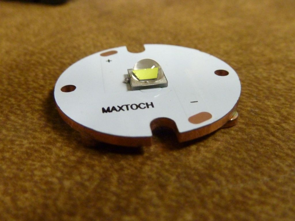
For the MaxToch 26 - I didn't finish it yet, but sized it up for the Y3 I'm working on, I'll have to re-drill one LED wire hole (poor positioning in the stock light) and possibly add a copper spacer to make up vertical space. I'll be modding the plastic alignment piece by cutting it down, then sanding the bottom to make it much thinner - it's way too thick now, keeping the LED further out of the reflector than it should be. It looks like the wires will clear the reflector bottom, so if the alignment piece is filed down, you can really get a nice positioned LED out of it -- meaning more inside the reflector.
if we add a resistor marked “0” will we gain anything ?
ImA4Wheelr wrote:grantman321 wrote:
. . . Bottom line… I need to figure out how to get this DMM set up right and then go from there. Are there any writeups on BLF about modifying budget DMMs for better accuracy?
I think we cross posted. Did you see my post 141. Your measurements are in line with Werner's measurements using a power supply (Post 143).
Tom E wrote:
But in my post #132 I said I measured 3.55A to 4.0A with the R100 resistor added (just like grantman321's Y3) - Werner's is with no resistor mod. There is still a difference in amps measured between his R100 modded Y3 and my R100 modded Y3.
That's why I asked in my previous post if anyone has measured with one cell. I don't know what the difference is about. It seems like what you said about the stock DMM's leads could be a big part of it. Stock DMM leads become a bigger bottleneck as current increases.
"0" resistors are jumpers - same effect as jumpering a wire across the pads. So if you do that over one of the driver resistors, you are nulling out the effect of those resistors. I didn't try it - might work at high amps, might fry something because of super high amps, might simply fry something because the driver can't take it - a risk, unless you don't mind losing the driver and/or LED, etc. Maybe someone tried it already? Not sure...
thanks for the info TomE , i prefer not to take the risk ![]() ,especialy for the driver will be very dificult to find another .
,especialy for the driver will be very dificult to find another .
If someone mods this, please make some pictures so that I can just do the same without hassling around to much to find a good focus.
Werner explained this above, but it’s quite possible to measure high current with thin leads… as long as there is plenty of voltage overhead available. Between voltage sag and the relatively high sense voltage which these buck converters consume and the voltage dropped on the thin leads grantman321 has run into his problem. When he measures 3A or 4A on a linear driver he’s probably using a very strong cell (doesn’t drop much under load) and a relatively low Vf emitter and just barely getting away with it. As you guys have all already mentioned, the problem is certainly going to be the leads. I just thought I’d expound on why grantman321 may have gotten away with 3A measurements.
An exaggerated example:
Stable 5v input for 3v output means the linear driver “burns” 2v. If small multimeter leads “burn” 1.5v, there is no perceptible difference at the 3v device. Current remains the same, output remains the same, and heat generation at the linear driver is reduced. Using the same setup with a 4v supply you’d notice a drop in output when you inserted the multimeter.
As I commented in the GB thread, there is never a good reason to short the sense resistors. There is nothing a short can achieve that a standard resistor mod could not. Figure out the drive current you would like to achieve and then do the math I posted in MRsDNF’s GB thread (post #417). Don’t forget that after you determine the target resistance you must use a parallel resistor calculator to figure out what you should stack!
missed that ,thanks.
Figured it out - as explained by wight, voltage drop was the issue. Tested both lights with two cells. Stock driver pulled 2.5A on high and the driver with an R100 added pulled 4.6A on high. Looks like two cells (or three) are needed to get the driver to perform with the resistor mod.
Not true for my R100 mod. I get 3.5 to 4.0A with one (only one) cell. You really need the heavy gauge DMM wire leads. I got it torn apart right now - in the middle of the MaxToch MCPCB upgrade - will use a XM-L2 U2 1A keeping the dome on.
As Tom E said, I don’t think you really grasped my explanation. The key is that we don’t have a lot of “extra” voltage (headroom) to work with when driving 1 emitter on 1 cell, especially with a buck driver. That doesn’t mean that the resistor mod won’t work. It does mean that you can’t accurately measure current the way you are attempting to.
That said, I can’t guarantee that every light is identical. Maybe you did get a bum light: one which behaves unlike the ones tested by Tom E and Werner. We know from collective experience though that standard DMM leads are always a problem, so I think it’s safe to assume that we’re right about it this time. Not that it means a ton, but look at the post counts of these people telling you that the DMM leads are the problem ;-).
Nah — I got what you were saying… Just looking towards the next step - if the DMM leads are causing a voltage drop such that the buck driver doesn’t have a high enough voltage to put higher amps to the LED at the LED’s forward voltage - the performance of the light (absent any interference from the DMM) would be good on a fully charged battery, but should degrade quickly as the battery drains given the voltage sag of the battery under load. So I was thinking that using two cells would ensure decent driver performance since Vin will always be sufficiently higher than Vout. Of course, as I said before, I’ve got barely enough grasp of all this to be dangerous, so I could be completely wrong.
On the other hand, a good cell with less voltage sag might be fine. But two cells would keep that Vin up high for sure.
Gotcha. In that case, you may be right about the performance problems with 1 partially depleted cell. Hard to say without some testing. As you said, 2s will knock the problem out for certain.
FWIW: While I know other people didn’t jump on the Y3 with the same intentions as me, I really didn’t/don’t intend on running the thing with less than 2s. It’s got a buck driver and extension tubes, so 2s+ was a no brainer for me :-). For 1s use I think I’d swap out the driver for something else?
Yeah I was initially one of those. After getting it in my hands I decided I liked the UI just the way it is and figured it’d be easier to look into modding the stock driver vs. trying to get another driver in there and rig up the momentary switch somehow? to make it function like it does when stock. So that’s where I’m at — modding the stock driver. I’m sorry for wasting y’alls’ time — looks like the additional R100 is exactly what I was looking for after all, and now with two cells everything looks ship-shape on the driver end. Time to reflow some emitters, shim up the mcpcb, braid some tailcaps and rock and roll.
I tried all kinds of resistor combos on this light. My 3rd one I have a U2 1A bin dedomed. Replaced the R150 with a R120 and then added a R100 on top (0.04186). 0.25 / 0.04186 is 5.97a? My meter doesn’t read after.
I was testing down quite a bit lower than that but it gets too hot and I lost one of the drivers when testing at 3 cells. At 0.04186 the sink can handle it fine with a 2 cell config and it’s about perfect throw on that sucker. Good balance. Noticed too you can get a better hotspot if you don’t go too far into the reflector. There’s a point where you get like a flower and that throws like crazy.
I wish I could keep this light but it’s going to my inlaw next week xd I’m doing two with a blfdd driver and retiring the mtg2. I didnt like this light for a flooder, my 15 led is good for that.
Some shots… It’s pretty awesome ![]()


Ok - finished the Y3 mods. Here's some details.
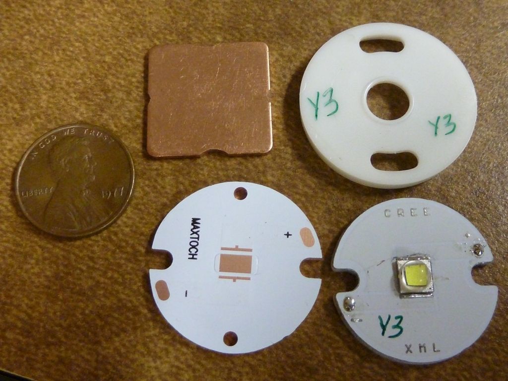
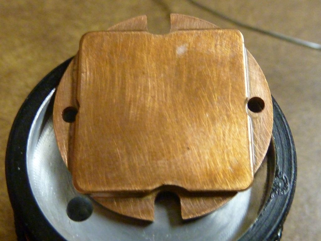
20 mm square, 1.15 mm thick, MaxToch star, penny for size comparison, and originals:
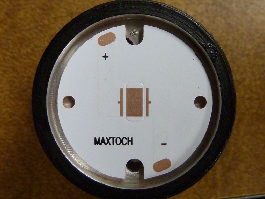
MaxToch 26 shown positioned. I marked a spot for drilling a hole. Original holes are not aligned well:
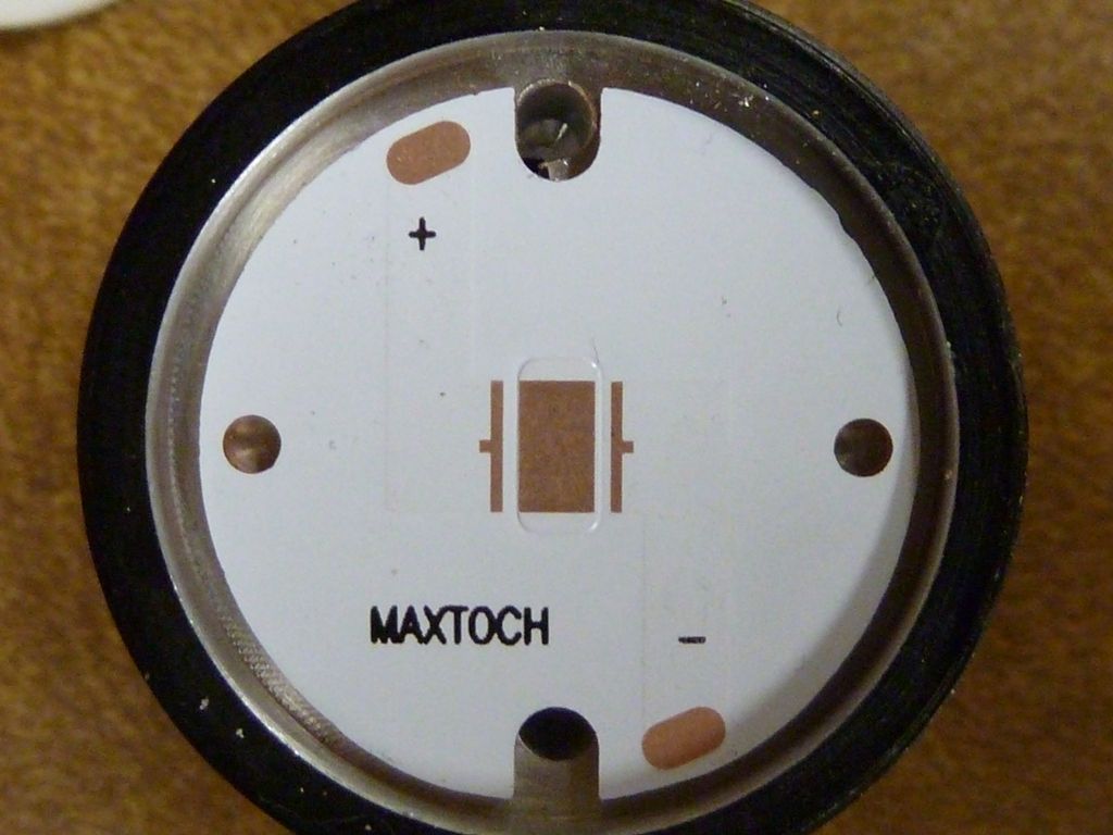
After the hole was drilled. Used my cheap drill press, ala comfy:
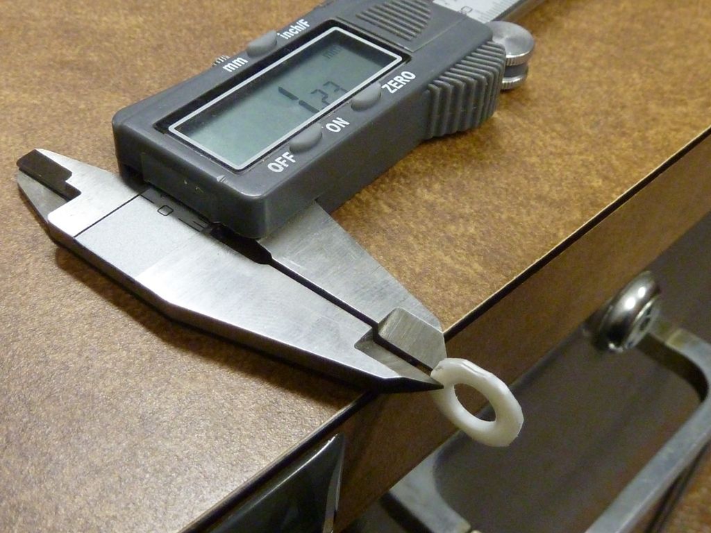
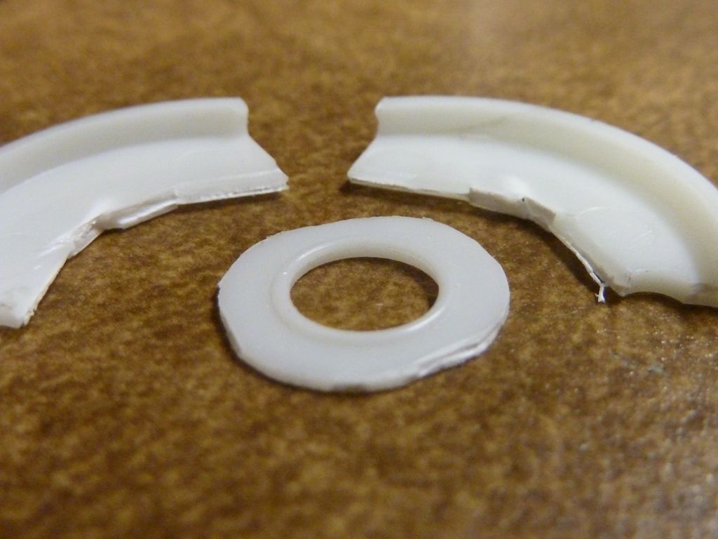
I cut and sanded down the stock LED alignment piece. 1.23 mm thick originally:
Sanded down to 0.75 mm. Used a pad of 100 grade paper, and rubbed the part on it:
Shown here with original pieces:
I reflowed the emitter (XM-L2 U2 1A) and the 20 mm copper shim in one step. Used solder paste, and frying pan, monitoring the temp with a hand help IR temp probe. Surfaces sanded to 2000 GRIT. When installed, I used GC Extreme thermal grease between the shim and shelf:
Backside view. I did more sanding after this pic, before mounting it, to remove that oxidation from the heat:
Though I did drill and tap holes, they didn't come out aligned up well, so didn't use screws - I could have widened out the holes in the MCPCB and got them to work. No worries with any possible shorts to the reflector. Nice low profile, and beam looked well focused compared to a stock Y3 beam - tighter hot spot. Also, the black hole doesn't appear til about 2" from the wall - nice for a Y3.
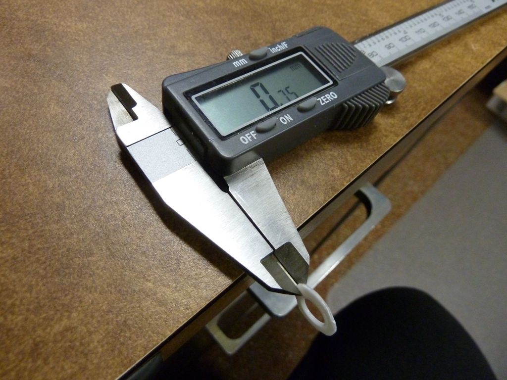
This has the stock driver with one R100, measured 3.16A at the tail on one KK cell, and 2.60A at the tail with two KK cells. Hhmm - the 26700 did not work -- seems too long. I thought all the Y3's worked with the 26700 - apparently not.
Results:
On KK 4200, 3.16A tail: lumens - 1,170 @start, 1,139 @30 secs, throw: 79 kcd taken at 5m
On two KK's, 2.60A tail: lumens - 1,428 @start, 1,380 @30 secs, throw: 95 kcd taken at 5m
Note: all my lumens and kcd measurements are "my own" taken on an older LX1330B meter - kcd taken indoors and lumens in a PVC constructed lightbox, accuracy can be freely debated (CYA all the way...)
Conclusions:
- note the 3.16A is sort of low, lower than I tested last night (3.6A) - can't explain, but used a different LED/MCPCB
- 2.6A at the tail for 2 cells is maybe 4.6-5.0A to the LED I'm guessing (totally guessing).
- this is with a UCLp installed, driver and tail spring copper wired
- results using 2 cells is pretty awesome - lots of light, great throw, but the LD-1 driver in my XM-L2 U2 1D Y3 still does better (higher amps, 111 kcd)
- total height of the MCPCB and copper shim is 2.63 mm, so about 1.15 mm increase. This was need to compensate for the reduction in the LED alignment piece, and the drop in height of the MaxToch compared to the stock MCPCB (about 0.5 mm less). I think the height/vertical dim turned out well - can full tighten the bezel and everything seems snug.
- I'm impressed it holds output pretty well in the first 30 secs - not much drop there - I've seen far worse.
- I like it, but don't like the stock driver UI - would rather have full control from the side switch, like the LD-1 driver or my (and others) custom drivers.
- Better mod upgrade would be a piggyback'ed BLF17DD with custom firmware, but then you lose the multiple battery capability.
Hope this answers some questions and gives you a better idea of what a mod can do for this light.
Copper shim bought in this nice assortment pack: ebay-45pcs-Laptop-GPU-CPU-Heatsink-Copper-Shim-20mmx20mm. Comes to about 25 cents each.
Thanks for the detailed infos on your mod. I will just do the same.
I never used a shim until now, have you bought this piece as a shim or just cut it out from a bigger part?
I have a copper sheet but it’s not thick enough, maybe I have to do a little search in the scrap parts box…
Edit: just searched a bit and there are tons of shims on ebay.
Werner - post above updated with link for the source of copper shims I used.