For a power cycle only, more simple UI yes it’s probably enough, plus with the attiny10 a 10f322 is a direct swap, same pinout between AVR & PIC. One thing tho is no voltage divider input so no voltage monitoring on the attiny10
With the initial design being for a dual switch light (courui is side switch only but I’ll be installing a tail clicky) it’ll have to be something bigger to run momentary FW.
Ok looking at the Vishay SL42 datasheet (covers the SL43 also) I see that theIF (AV) rating is different from Al to FR4 and that on FR4 its only 4A, is this still safe to use at 8A output on an oshpark board (albeit with a large Cu pour) considering that?
6 Diodes inc Schottky 10A 40V PowerDI™ 5 (I choose this slightly more expensive and higher rated diode for a few reasons, one being this package is smaller than the more common DPAK and also because while its more expensive individually it offers a better bulk discount)
7 AOD510 (exceeds all requirements, has great low RDS(on) and I have a hundred of them)
8 For my use a 12F617 but probably make an ATTiny13A version at the same time for everyone else
10 470ohm 0603's cause again thats what I already have on hand
Good catch, fixed. And while I’m waiting for either one of my Courui’s to get here or for someone to hook me up with measurements, just for S&G’s I thought I’d see if it’d fit in 26mm, definitely not even close!
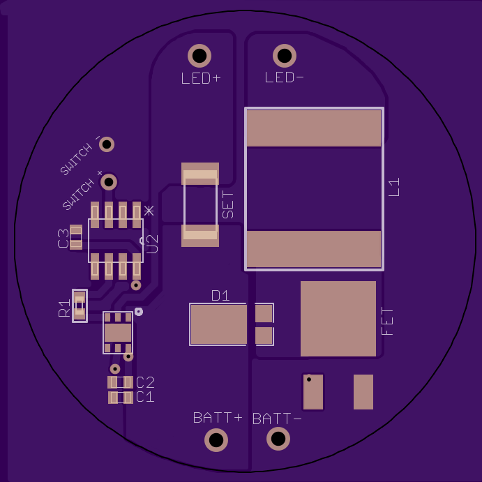
Very first draft of the very first board, AVR based for you guys (cause if it was for me I’d make everything in PIC). Wish I cold be working on the Courui driver but no one’s yet came threw with measurements or a driver I can borrow…
Notice there is only one remaining air wire (which I cant find, even when I turn off all layers) and it almost passes DRC (only has a couple of clearance errors)!
42mm for TK61. I have some more components to add to the other side including a smart latching FET based switch to kill the buck chip (since it doesn’t have a low power standby mode), that’s what the 2nd e-switch will do, one for power and one as the normal AVR momentary FW input. That will all require major changes, I just needed something to show for what I’ve got in this already so I threw this together.
Sorry C_K, I loaned my Courui to a mate for the night. I should be getting it back tomorrow, so I can give you dimensions in about 24hrs from now if need be.
excerpt from OP in Teardown and Mod Thread of Courui XML2 Aka “Big Head 3x18650 Side-Switch Thrower”. See the bottom of the OP for two pictures of the driver, one of which includes a good view of the driver cavity. The ledge looks pretty meaty, so watch out for that. That’s probably an important measurement to get your hands on.
Yes I need everything, I also need the spacing of the cells so I can get that figured out.
Question, will it be possible to drill and tap mounting / ground holes (2 or 3) in the ledge the driver sits on to be able to screw it down? With the series conversion driver orientation will be critical.
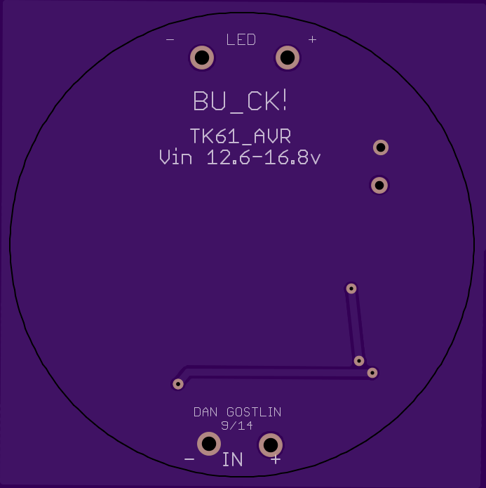
This is what I’m working on in the mean time, there are several components missing for a smart latching switch (that will run off a coin cell) that uses a FET to kill power to the MAXUM chip, this will allow both buttons on the TK61 to work as normal, one as power (turn the FET on/off) and the other as the one mode change switch everyone uses for the different AVR momentary FW’s. The ATTiny13A wont control the FET at all, the Li coin cell will power a small iC to handle that part.
As you can see this is version 0.1, there are several issues I see right off the bat so still very far from having anything to order.