It depends on what level you’re trying to determine efficiency.
In any PWM controlled light the lower the amperage is on high the more efficient the system will be in the PWM modes since the driver only has to switch 10% of 3A as opposed to 5A for example. As TomE already stated leds are more efficient at lower amperage and thus the higher the max amperage the less efficient the lower modes will be since the LED is still receiving 5A but for only 10% of the time for example.
To answer your second question it is more a case of safety rather than efficiency when children and/or inexperienced people are involved since most FET based (direct drive) lights run extremely hot on max. I would stick to lower output, current regulated (7135) lights for people unfamiliar with such hot rods.
Yes - of course a 7135 is a current regulator, but in a typical Nanjg/Qlite 7135 based design for one cell and one LED, it can easily fall out of regulation, therefore run at lower amps. For example, I can build up a 5.6A Nanjg driver with 16 350 mA 7135's, but for a Panasonic B cell and an XM-L2 on copper, I cannot achieve getting 5.6A, maybe only 3.5A or 4.0A at tops -- it falls out of regulation -- is this the right terminology?
I didn’t get a connector so soldered the wires on and got it working first try! jinx … Backed up the firmware on the chip following the wiki. But wanted to ask- what software would you recommend for programming and a good firmware to start with that supports the eswitch? I seen in the wiki they say the BLF-VLD is a good start. I seen comfy had a cool firmware in that dropbox Tom posted too.
Is AStudio 6 any good? I’m running all this in a vm using xp (I know but… when in rome) if that matters.
OoooO Thanks comfy… Installed Eclipse Luna- But it says my hardware doesn’t support the tiny13a when I go to load the mcu. Guess have to manually flash the compiled. I got quite a few different source files it’s kind of out of control! Jonnys and Toms had some nice ones I went through the other night. Dr Jones had like 3 of them that were pretty nice and strait to the point too.
I gotta say it’s nice to see people sharing source and bothering to comment on it too
That was a nice thing to do man… I finally got eclipse working and building, burning the firmware but I’m not up on the fuses. I found a good site to set the bits you want but I don’t want to brick it. http://engbedded.com/avrdude
I see in the avrdude bat you set the Upload Fuse 00 low 75 high. And the memory lockbits 255? FF Is that what the -UhFuse setting does in avrdude?
Maybe I should set the bits once in dos and not set them in Eclipse. It only seems to work using Tiny13 anyway and I can see something going amok there.
Getting eclipse building was kind of a pain in the ass. I finally got it to build and burn without errors, when tried to upgrade avrdude- it went back to spitting them out… So using the older version and put MinGW paths into c paths and symbols. It plays nice with the debugger finally.
I just saved a snapshot of the vm. Looking at your code. I switched STAR3_PIN and SWITCH_PIN around so I don’t have to reconnect that thing but going to test in the morning. My wife is trying desparately to get me off this computer. She texted some leg pictures but it’s nothing I haven’t seen a billion times lol
Are you on Windows, or not? Hard to figure out just from indirect stuff. If so, just double-click the .bat file and it opens avrdude and does everything for you, that's what it's for, so you don't have to figure out and type the commands each time you want to flash the same firmware. High & low fuses are already specified, lock bits are not because who cares with an open-source firmware?
If you're on something else, open the .bat file, copy the command string, and paste it into the avrdude window (assuming you've opened avrdude from the same folder where the .hex file is, otherwise navigate to the right folder first).
Ah nm… I see now It’s 75 hex low and FF high, leave the memory lockbits alone. Yeah using Eclipse, just wanted to make it all automated without using the command line, build and burn you know. I’m a linux guy but running this in a vm on a stripped install of windows xp. I could move it over to linux I guess, but this is good enough.
Yeah I’m still at the start ready to run. I haven’t really got around to modifying code yet, but it should be fun getting the modes I want. Was thinking of making the yezl ramp up and down between clicks and put in your crazy fast strobe on hold of the eswitch.
The F6DD beta is a tweaked version of ToyKeeper's SRK firmware. Mode order default changed to short press = higher, long press = lower, long press duration dramatically shortened (from I think 35, down to 17), press & hold and it steps down levels until you release, or it keeps going all the way down to 'off' if you keep it pressed. It still uses her hybrid thing of phase-correct on levels 1 & 2 (gives less light output with the same PWM number, so helps get a lower low/moonlight), and the non-whiny fast-PWM on all other levels.
If you go messing with the fuses without also changing all the relevant bits to match you'll totally throw off the switch timing. So don't do that. No need to change any of that.
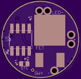
A real GND plane (on both sides) this means no more pulling off the thin gnd rings, it also means you can scrape a little mask and have a GND point almost anywhere on the board.
GND plane has “thermal’s” on the lower power components (for easier soldering) but is solid for the FET’s source leg and the batt nagative input via to supply the necessary higher current (this was not easy to make)
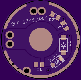
A dedicated zener pad, no more stacking (simply leave unpopulated for 4.2v builds)
C1 is in the proper position to eliminate “boost circuit” issue so no more gate resistors
“Star’s” are easier to short with just solder
Dedicated batt- input via (used for piggybacking)
Has a set of 1.1mm LED lead via’s (sized for 20AWG wire, even 18 will fit), this makes multi-emitter builds less of a pain.
Dedicated SW+ input via on pin3 for MOM FW’s
Batt+ spring pad is 8mm but only 5mm exposed (the size of standard 105C springs and those brass buttons), scrape to expose the full 8mm
Note this is not a mod of the V2, this was a total redesign
Ahhh - CK, this does look like a real killer!! Think it has everything, and better? No more 2 or 3 versions? This is one master 17DD, all-inclusive? Hhhmmm. wow.
Big Q - tested yet? If not, how risky? Should we wait?
It will work as a zener, with no possibility of voltage monitoring (which isn't important to most of us anyways). Maybe it's time to just switch to a layout where the voltage divider doesn't pass through the diode on any of these, since we're all using custom programs anyways. Same resistors could be used for single cell with a slight bump in the ADC values.
Ahhh, ok, that's a "good-to-know" loss ??? You are losing me here. Speak slower . Why is it breaking voltage monitoring? Why is that not a major loss? - thought that can be worked out. I can't follow this....