Right
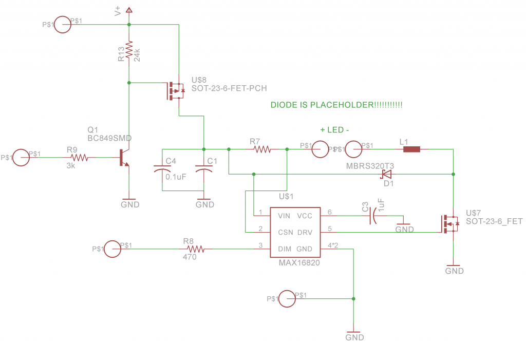
these two form a voltage divider which sets the output voltage by making a 3.5v output produce a 0.765v level at the feedback pin, which is the setpoint the chip is regulating to. The chip has no specific output voltage, and in fact it doesn’t know or care what the real output is, it just regulates to 0.765v on the fb pin. The manufacturer does this so that the same chip can be used to produce any voltage you want.
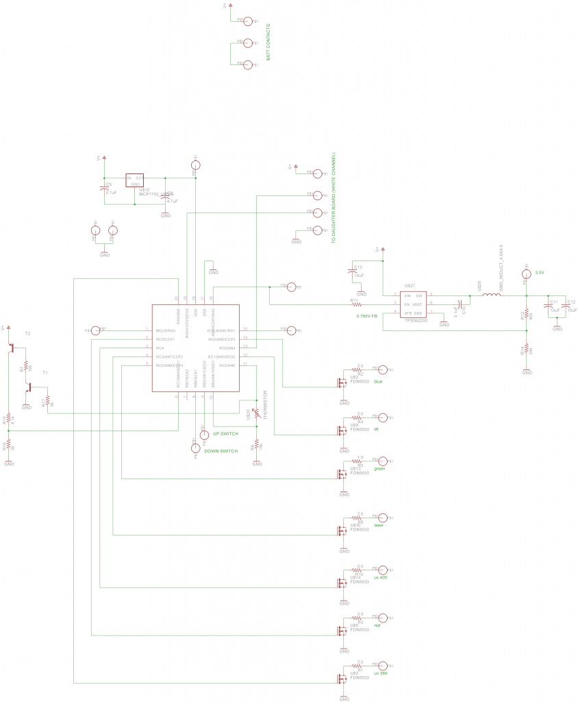
You’re thinking of constant current regulators, but this is constant voltage for exactly this reason. The led currents are individually set by their resistors next to the FETs, so you can have any number on simultaneously and their currents won’t change. The regulator will supply whatever current it needs to in order to maintain 3.5V, so yes it will compensate automatically. The buck regulator is set at 3.5v because from this voltage I can easily set led currents with resistors while minimizing the wasted power because the voltage overhead is low.
It can supply up to 3A total for the color leds
Q1 is necessary to protect the microcontroller from high voltage and to allow the FET to completely shut off. If you connected directly to the FET gate, when you tried to turn it off by setting the uC pin high, the FET would still see (Vin - Vcc) which could be as high as 12.2-3.3= 9.3V, so it wouldn’t turn off. You could then try setting the uC pin to high impedance and let the FET gate pull-up resistor turn it off, but then your uC would see as much as 12.6V on the pin, which would waste current at best and destroy the microcontroller at worst.
R9 limits base current into the BJT. BJTs are current-controlled unlike FETs so you must regulate base current to keep from destroying them