I'm excited about this as Low Voltage Protection it is much more critical for these high voltage lights. In a single cell light, it gets dimmer up in the 3.9's. Of course, you still have the risk of the light being on while your not aware. So LVP helps with that. But in a 4S light with a single emitter, you can go low while using the light. I'm really glad you shared the knowledge to help protect against that. I really need to find a decent budget power supply.
For the MCU, I guess you all don’t have pinouts, but do you at least know where some of the pins on what you think is the MCU chip are going to? Just curious if that would help identify the MCU?
I’m not aware of an MCU in that package. At all. I think it’s… what, a 10-pin TSSOP? I looked through the product lines for Atmel, Microchip, and I think also Zilog. I couldn’t find anything in that form factor to compare the pinout to! I’ll admit that I had trouble looking through Zilog’s portfolio.
Anyway the point is that step one is to at last identify an MCU that can physically match that landing pattern.
Does the one you all are thinking is an MCU look like the 10-pin in the pic in this post (on the 266050 driver):
I’m a newb here, just dropping in, but I was thinking that if you could get some traces from the 10-pin chip to wherever they go, that might give you some idea what the functionality of that chip might be?
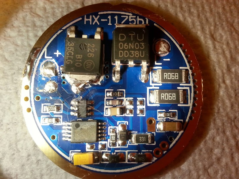
Hi Ohaya. The 10 pin chip is definitely the MCU. No clue which one though. The pin functions that I know are as follows (looking at the top of the chip):
PWM Not Used
Not Used Not Used
Ground Not Used
Positive Power Supply Don't Know, but traces appear not connected to anything
Not Used Don't Know, Looks like it could be used for Voltage Monitoring but traces appear not connected to anything
Here is the orientation of the chip for the above pin out:
Good call ohaya. Looks like the pinouts match to me - so it’s one of the μPD78F920x. Timer output for PWM on Pin 1, GND and Vdd on 3 & 4, and analog input on 6. That’s all the functions ImA4Wheelr described.
I guess the next question is whether we know anybody who can tell us about flashing these things cheaply.
You all might ping Dr.Jones, to see if he has any firmware that’ll work, but although I only looked briefly, these chips look pretty proprietary, from the old NEC days.
Meh, I’m not actually interested enough mysef. This is the only halfway decent driver I’m aware of which uses this MCU, although IIRC we’ve seen it on at least one other driver, I think it was a DD driver.
Good find on the actual MCU, now we can safely ignore it.
Has anyone tried this driver with the XHP70 (6 volt configuration) yet?
Since RMM has done a lot of measuring and experimenting with this driver using MT-G2, I'm hoping he wil drop in with some input. Buck drivers are supposed to have less ripple when supply voltage is closer to Vf. Did the voltage spikes with 3S cells and one MT-G2 appear potentially problematic for XHP70?
No problems with the XHP70. I've only tried up to about 8A with one, but it can handle it just fine. Even with a huge 20% ripple (this one is generally 10% or less) you're still under 10A, which the XHP70 can handle easily.
I really need to update some of my findings in this thread. I got the ripple down to a minimum, but it was around the same time that the new XM-L2s started coming out, so even though the ripple was negligible (~1%) it would still blow them at 7A, because even direct drive the LEDs couldn't handle 7A anymore. I turned them down to 6A and all was good.
Thank you RMM. Good to hear that. I was expecting a different answer based on you earlier reports in this thread.
I really want to design a board with a different MCU that is loosely designed like this board, but I'm still early in the learning curve for Eagle. If you ever go down that path, I would like to try to help with testing. High current bucks are what I am always interested in.
I've been focusing mainly on the small ones and have learned a ton since I started fumbling with this one a year ago. The cheapest route would probably be to just downsize this board then use these for donor parts. Buying good parts individually will end up costing more than what you can buy these boards for! If your goal is to power MT-G2 and XHPs then you have a lot of wiggle room when it comes to the output waveform, but if you are planning on the smaller 3V LEDs then things have to be good to go.
If you are looking at designing one, then I would recommend reading some of the datasheets, especially the TI datasheets, regarding circuit layout. When you start getting into bigger switching converters at higher switching frequencies layout matters a lot--you can't just hook the wires up and expect it to work correctly.
Was playing around with LVP on this driver a couple weeks ago with what appears to be some success on my PS, but that PS is cheap and gives weird results. Using 100K and 5.1K resistors and I don't remember the numbers I used in Star Momentary with 4S cells driving an MT-G2.
Need to test with cells. Been running with 4S cells since I put the light together then, but they still have not drained enough. I'll report back when I have more info.
RMM,
Back in Post 153, you had some great info about ripple and you sound like you have learned more about modding this driver since then. Hope you don't mind a couple questions, if you have the time to respond:
When you refer to output caps, do you mean just across the LED Leads?
Regarding inductor positioning and shielding, do you know if one can get some limited shielding using aluminum foil or something between the Leads and the inductor? No biggie if you don't know, I will be googling it soon.
Do you have any update suggestions for this driver?
EDIT: I accidentally connected a stock HX-1175b to 2S XM-L's on copper last night with 3S cells. The emitters fried instantly.
I've got a lot more understanding now than I did last year so I would have to revise some of my earlier statements. I had lucked into a few things working, which means that they do work, but it doesn't mean that they were ideal. I definitely don't recommend anyone using a 47uH inductor on one of these unless you want a 1A to 2A output. You want something more like 8uH-15uH for the ~6A I was shooting for.
Some of my initial issues were due to overcurrent, plain and simple. I started playing with these at the same time that the vF on the XM-L2s started to change, lowering the maximum current significantly (You used to be able to get 7A out of most of them---now you are lucky to get a lot of them to survive at 6A).
Output caps: Yes, across the LED leads. This will greatly decrease the output ripple current while maintaining the same inductor ripple current. This is where you always put the capacitor(s) on a hysteretic constant current buck driver like this one, which uses the QX9920 IC, but it also applies to the MAX16820. You have to look not only at the capacity and overall ESR of the capacitor, but you also have to look at the ESR at a particular frequency. Generally, smaller capacitors are more effective at higher frequencies, while bigger capacitors are more effective at lower frequencies. Putting too much capacitance or high ESR capacitors across the terminals can actually increase output ripple (and will also decrease the dimming range). With an MT-G2 I wouldn't worry too much about adding anything, since it is a tough LED to kill. With an XM-L2 you can probably eek a bit more out of one without frying it, but they are still current limited. If you're using ceramics, I'd go with a 0.1uF and 1uF ceramic capacitor (you probably already have some 1uF capacitors laying around). You can parallel more capacitors up to a point, but the gain diminishes quickly.
I'm not sure about the inductor shielding. I'm not sure if foil is a good idea. On mine I was just putting some heat shrink tubing over the inductor to keep the wires physically farther away from it, but that isn't the same thing as really shielding the inductor.
If you are looking at changing inductors, I would use the formula from the TI datasheets or the the Maxim datasheets to determine what your switching frequency ends up at. You have some wiggle room with the factory inductor.
This is still a heck of a beefy driver for the money. It is easy to piggyback onto and can handle a lot of current. You can turn the output down a bit by changing the sense resistors (I=0.25/R). The main downside to this driver is that it is hard to turn into a good momentary driver due to the high quiescent current drain. You couldn't buy the parts to build one of these for the price you get these for, so they're still a sweet deal.
^ Thank you for more great info. Very helpful. I won't pretend to understand everything you said as you went deeper than my electronics knowledge base. I will be googling and trying to learn the stuff I don't understand. Nothing like a real world problem/challenge to encourage learning theory.
I've made about a half dozen lights with this driver and all of them are momentary switches. Definitely have to use discipline locking them out. All the drain appears to be in the up front voltage regulation that feeds the MCU and part of the buck converter. It's a very common system using diodes that seems to be in every buck driver I have encountered. Is that something you have addressed in your buck drivers that you are developing?
I'll look for my notes, but can't promise anything. I know I scribbled one out a long time ago, but I never go around to verifying it. It's hard to see the traces with the large copper traces on the battery side.
I have prepared one in easyeda and it is more or less I can see under the light and by the use of my digital multimeter, so I can share it to work it out together.