
This driver is improved version of 5Amp linear pwm-less driver prototype also called LD-1.
LD-1 prototype thread with a lot of useful info about theory of work and advantages of true constant current driving:
BLF members reviews(HKJ,TomE,djozz,Racer86):
Selling thread here:
Features:
-input voltage 2.8-4.35V
-5 Amperes(default) current
-off-time mode memory
-no components on spring PCB side
-place for decent size (up to 8mm bottom diameter) spring on spring side pcb
-PWM-less TRUE CONSTANT CURRENT on all modes-no acustical or EMI noise
-significantly longer run-times on lower modes compared to PWM-based(FET or AMCs) drivers-even >2x possible
-stays in regulation on lower modes for longer periods of time compared to PWM-based(FET or AMCs) drivers
-~50% more overall efficiency on low modes compared to PWM based drivers(for 5Amp )-based on HJK's prototype test
-<6mohm power mosfet
-pmos reverse polarity protection
-calibrated voltage reference and temp. indicator
-less than 100uA parasitic current in sleep mode (40uA typ.)
-enough space for easy led wires soldering(up to 20AWG,22AWG recommended)
-4-layer PCB for better heat distribution
-2.2mm total thickness(including 1.2mm PCB),16.9(+-0.2mm)mm diameter
-2-step low voltage protection(3V-restricted power; 2.8V-sleep)
-driver over-temperature protection (~105C)
-simple,intuitive UI,no disco modes
-modes: ~10mA-100mA-1000mA-5000mA or ~0.2%-2%-20%-100%,standard half press to increase mode
-0.2% disable via solder "moon" 1
-90sec timer on high(5Amp) enable via solder moon 2
-tailcap switch and electronic side switch capable,independently or both at the same time with single firmware
-three separated e-switch user interface types(rather than one complicated)
E-switch user interfaces
1.)UI_1-
-normal button switch press increases mode: sleep->(mode0)->mode1->mode2->mode3->sleep
-double press decreases mode
-long press from sleep->max mode
2.UI_2
- improved ramping UI(based on RaceR86 suggestions in his prototype review thread)
-normal switch press from sleep->last current setting
-long switch press from sleep->minimum current(~10mA)
-when on,~0.5sec switch press activates ramping up or down,release switch to stop ramping;pressing switch again for >0.5sec- driver ramps current in opposite direction
-quick double press->current goes to max or min (alternating,just like ramping direction)
-when on,normal press(<0.5sec)->driver goes to sleep
-one very short blink at 50% current,2x blink when current=max.
3.UI_3
- double press increases mode
-single press->driver shuts down
-single press from sleep->last used mode
How to set UI:
-turn the flashlight on and hold button switch pressed for more than 10sec(some blinks).This works in any mode and UI type.UI is changed to next one.Repeat to get UI you want.
Other:
E-switch protection:
-if e-switch is pressed for more than 20sec(accidentally in pocket,bag etc.),driver shuts down
Blinks
Low voltage warning 1(2.80-3.00V): 5 blinks,5Hz->current is restricted to <150mA(so you can still use 10mA and 100mA modes)
Low voltage warning 2(<2.80V): 10 blinks,5Hz->driver goes to sleep
Driver high temperature warning:10blinks,10Hz->driver rapidly reduces current to 1Amp(if current was >1A),and then further regulates current until temperature drops below temp threshold(but max. current is 1Amp now)
Ramping current is 50%:1 blink,10Hz
Ramping current is 100%:2 blinks,10Hz
UI_change:3 blinks, 2.5Hz (this happens after e-switch is pressed for more than 10sec)
E-switch protection:6 blinks 2.5Hz (this happens after e-switch is pressed for more than 20sec,driver goes to sleep)
Cooling
Note:This driver is designed for single emitter(XM-L2,XP-G2 and similar) and single Li-ion cell.
In practice, maximum dissipation in driver isn't at max. mode,but when current is in 1-4Amp area.
Tests show that driver can handle generated heat(0.2%-2%-20%-100%) without any additional thermal "upgrades",but generated heat strongly depends on battery-LED-wiring configuration. It is always good idea to keep driver as cool as possible,so I strongly recommend use of thermal interface materials,such as these cubes:
In ramping UI,current can have any value,including 2-4Amp range,and it that range dissipation can be quite high,so if heat conduction isn't good,high temp. warning may occur.If you want to use ramping UI(especially in mid current range),better thermal upgrades are mandatory,like potting,small heatsinks on mosfet,etc. or use expander PCB described in tips&tricks.
Driving triple or quad XM-l2s, XP-G2s,XP-L2s or similar in combination with resistor stacking would generate more(too much) heat in driver(mosfet) because of lower Vf.
If you want to drive multiple emitters at higher total current(for ex. 10Amps),don't use this driver in stock configuration-use expander PCB,see tips&tricks.
Tips&tricks
Higher current and/or driving multiple emitters(in parallel)
https://oshpark.com/shared_projects/lVxSLRMA
Some BLF members asked about driving multiple emitters(in parallel) with high current,for example triple xp-g2s at 10Amps or xm-l2s at 12+Amps.This is too much for stock driver because of relatively poor mosfet cooling("hollow pill" mounting style has very small contact area for heat conduction).But if we put mosfet on another board and ensure better heat connection with flashlight body,it's possible.
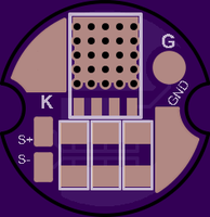
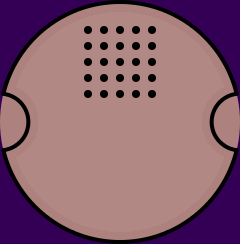
Upper board is 15.5mm PCB "expander" for LD-1. Board contains power "part" of driver: mosfet and place for 3 sense resistors.It is designed for mounting on bottom of pill(with thermal adhesive materials,such as fujik,arctic alumina,double sided thermally conductive sheet...).This way mosfet has much better thermal connection to flashlight body which allows higher power dissipation.
Important notice:bottom of expander pcb must be electrically isolated from GND(flashlight body).Kapton tape,mica sheets and other similar stuff should work,but I think the simplest solution is double sided self adhesive thermally conductive sheets.
There is a place for three 1206 sense resistors for up to 15Amps of current. Required total resistance can be calculated form this equation: R=50mV/I, where I is desired current.For example if you want 5Amp put just one 10mohm resistor on expander board,7.5Amp,put one 10mohm and one 20mohm resistor,10Amps->two 10mohm resistors,15Amps->three 10mohm resistors.
Mosfet should be NXP PSMNxRx LFPAK56 series with 4-5mohm Rds on.
Sense resistor are welwyn LRMAM1206 series(LRMAM1206-R01FT5,LRMAM1206-R02FT5...)
Note: Currently I don't have these boards or extra parts for sale,so if you have plans for using expander board,you must order board from OSHPark and parts from your local distributor.
Connection diagram(not the nicest wiring,this is just for testing purpose):

Few notes and explanations:
Sensing resistor is removed form driver.No other modifications on LD-1 pcb are needed(you could remove FET if you want to re-use it on expander pcb,but this is not necessary if you have fet for expander pcb).
-keep S- (black) wire as short as possible(<1in if possible) and not thinner than 24awg(the higher resistance the larger the current sensing error)
-other three wires that are connected to driver S+,G(means gate) and BATT+(Vcc or power supply for driver) could be thin since they don't carry any significant current
-as you can see main current now flows through expander PCB via two wires:GND(black) and K(to cathode,red wire) and they need to be thick,how thick depends on desired current
-for testing purpose expander pcb is mounted on heatsink with double side self adhesive sheet(~150um thick 3W/mK in this case)
(you can see two blue crossed wires they are not needed,other two wires white and brown are for side switch)
Lower moonlight
If moonlight current(~10mA) is too high for someone,it's possible to lower current in moonlight mode,but at a cost of efficiency.
Solution is very simple:just put resistor parallel with led;it will "steal" (bypass) some of the current from led,how much depends on resistor value,equation is I=Vf/R. For example 500ohm resistor would steal ~2.7/500=5.4mA(resistor will steal that current at all modes,but this is negligible on other modes).
Important fact is that total current consumption remains the same. BTW this doesn't work with pwm drivers because current is always max(Amp range),just pwm-ed.
Connection diagram(older prototype pic but connections are the same)

