Thanks WarHawk-AVG! The difference in size probably a little more striking in person where volume is more easily perceived. LPAK56 is also much shorter than DPAK.
I use your old version with the bigger dpak FET, due to lack of the new FETsize.
but anyway I just played a bit with the driver, I just assembled the single 7135 on PB0 and the Two 7135 on PB4 because i am afraid of fusing the reset Pin…because I have no HV programmer yet.
I modified the STARMomentary firmware a tiny bit:(i always started comments with “changed” so it could be searched easyly)
the above code does following modes: 0,MOON with PWm over single 7135, 350mA over full powered single 7135, 700mA two 7135 fully powered, direct drive with FET fully driven…
possible problems:
modes are uint8 which only allows values between 0-255 so I have two give TWO7135ON a value which cant be used longer as a PWM number
maybe it would be more neat to make a third row of modes:MODES, ALT_MODES, CONSTANT_MODES
So that if the first two are zero the last line would only switch the groups of 7135…
is there a cheap fuse resetter or HV programmer available? is this still possible if everything is assemble(like on a soldered driver) like ISP or do werun in other problems as well
Thanks for working on this Werner! And I’m sorry that I have not become motivated enough to attack the code portion myself.
I’ve been assuming that we’d have enough space to use array for each output, but I am quite possibly wrong. Like I said, I really should write some code instead of talking so much. So the modes you described would have looked like this with the arrays I envisioned:
PWM-a {0,15,255,0,0} single 7135
PWM-b {0,0,0,0,255} FET
Binary-a {0,0,0,1,0} two 7135s
Binary-b {0,0,0,0,0} not connected
Otherwise I think you’d need logic to interpret the CONSTANT_MODES array and figure out which binary pins to pull high or low.
On the fuse resetter question - I do not think that there is a really cheap way to do it. If <$9 EDIT: <$5 USD is cheap for you then you can use an Arduino with a transistor in the way described here. There is no cheaper way that I am aware of, and I don’t think that there are any HV programmers below $30 USD.
that is how i thought would be neat.
PWM-a {0,15,255,0,0} single 7135
PWM-b {0,0,0,0,255} FET
Binary-abc {0,one7135,two7135,four7135,0} whatevercount of 7135 fully enabled and the logic with acase construction
the code now is 764bytes I cant estimate if a case construction would be to much but I guess not….i will try later
it would be cool to have a small fuse resetter which works with a single supply current and has a standard ISp socket so that i could use my soic8clip……
i will read the tiny datasheet later to see why nobody does that…
I think there is enough space for the case construction. I’m just not sure how clean it will be, especially in case the number of 7135s changes (different boards or builds). Maybe you will show me.
A standard Arduino board such as this one or even this one has a 12v to 5v regulator onboard. If you power it from 12v AFAIK the only things missing are the small transistor and the protection resistors and the actual header to connect your programming harness to.
I just added a case construction instead of using the TWO7135 constants I went with simple numbers so that the columns of the modes match. I named the additional array const_modes(not so happy with this name…) and just initialized everything like it was on the other modestypes Jonny mac has made.
seems to work with three 7135.
different numbers of 7135 will of course make it difficult because you would have to “calculate” which you have to switch on when…For now I can live with one to 6 no PWM adjustments….there are no pins left so i guess the only possibility would be stacking and then the people have to do the math themself…that would be to complicated because some combinations would be excluded and others changed…that should be done before programming and i have no clue how to do that…
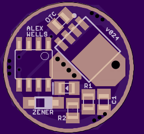
I have updated this board with a thicker GND ring on top and new, more legible silkscreen for D1. I thnk I also tweaked the copper pour for LED- to flow slightly better into the FET pad - a purely aesthetic change. These changes are based on changes I implemented for the A17DD-SO8 driver. https://oshpark.com/shared_projects/pcTBBHOv
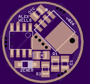
When I came over here to post the v024 update I saw Werner’s post #61 again. That got me thinking, so I updated the driver to v026.
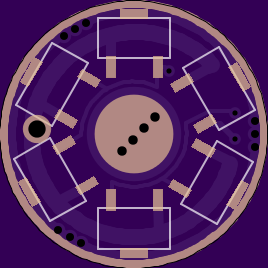
Werner is using only 3x7135, controlled by 2 pins on the ATtiny. One 7135 connects to Pin5. The other two 7135’s connect to Pin3. In v024 and earlier this makes the bottom of the board lopsided because all of those 7135 positions are next to each other.
To combat this I made it easy to drive all 5 of the non-PWM 7135 positions from Pin3. I moved the via next to Pin1 a little bit to make the trace easy to cut on top of the board (so it’s not visible after the build). I also ran a trace from the via over to a solder jumper at the pad for Pin3. You should be able to place a small bit of solder there and still operate a clip. If the jumper requires too much solder and makes using an SOIC clip a pain I’ll tweak it.
Once you’ve cut the trace and soldered the jumper you can then run 3x7135 like Werner did, but in a nice triangle configuration.
There appears to be an error in the OSH Park render such that the BLF text is spun around. I’ve emailed support about this. It works fine in GERBV. (No it doesn’t. What was I thinking? I’ll upload a version with the text in the correct orientation!)
I wasn’t brave enough yet, because of the fuse thing. And I was to lazy to build a fuse resetter…
so there is just the above posted version which works but without support for the 3x7135 group, but it doesn’t ruin the tiny for sure.
Technically I think you can run the dual-PWM STAR firmware with these, just like RMM’s Moonlight Special. It’ll only take advantage of a single 7135, but you should be able to achieve consistent, low, moon modes. AFAIK that should work for ontime and offtime clicky builds.
Werner’s momentary code from post #61 should work; Werner has tested it but I have not. That code is for controlling 3x7135s and can be easily adapted for 2 as well with the old hardware. With the new hardware Werner’s code can be adapted to run as many as you want but they’ll still be controlled together (for example 1 with PWM and the other 5 as on/off together).
Oh, also I don’t think Werner made it clear but that momentary firmware could also be used for one-shot programming of ATtiny13A’s with our normal USBASP programmer. If you know your modes configuration it seems to me that Werner’s firmware is good to go… you just can’t reprogram.
I probably make it sound more complex than it really is. There’s really nothing super complicated about it the design, it just turns different quantities of 7135 on and off, plus has an FET to turn on and off.
Hi guys, excellent work as usual! Im just wondering wouldn’t that be excellent driver for one XM-L2 if we put 8 7135’s and use Attiny13a to control it like 1x7135, 1+3x7135 and 1+3+4x7135, so then we have quite nice efficiency on all modes right? Maybe this 1x7135 should go with PWM if possible. Next we need someone who can draw this driver to Oshphark and little more code. No need for FET, we could stack 7135’s if more power needed right? What do you think?
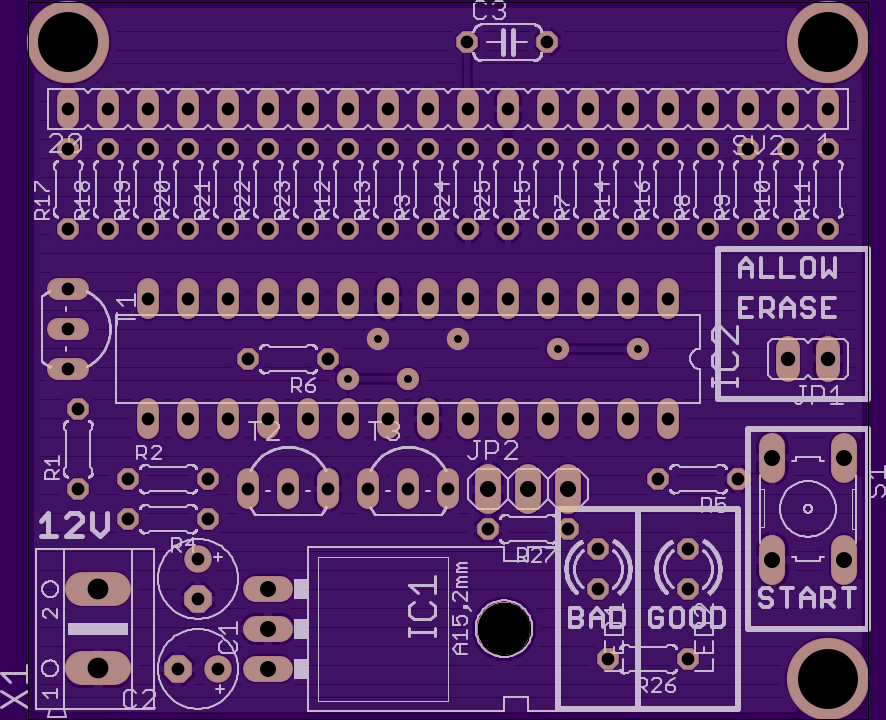
Atmega fusebit doctor (HVPP+HVSP) Short board Warhawk’s tweak
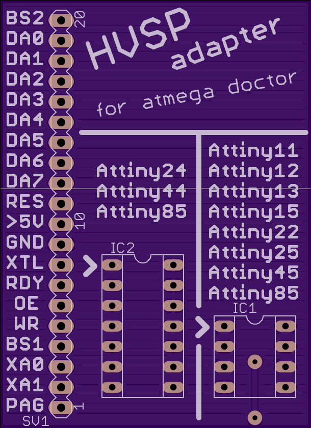
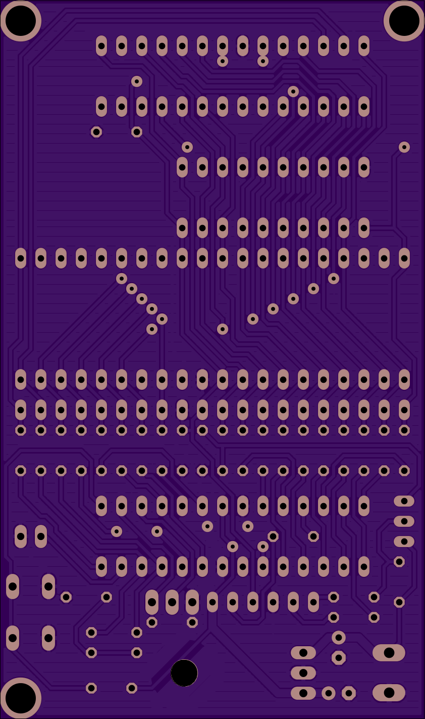
adapter_HVSP WarHawk’s tweak
Can cut everything off above DA7 for even smaller board
I think on the guys later revisions, he fixed the problem with one of the traces on his board that got cut by a drill (this is his unmodified full size board [other than me tweaking and filling the polygon pours between traces], look at the very bottom in the center, the power trace runs right thru a drill hit) [I did mention it to him in his thread, I think he fixed it, but my tweak I re-routed it for the “short board”]