This might help.


Hmm, that does look like a good start. Unfortunately I’m not up for much beyond a straight clone, and the pics in that thread are of sanded parts.
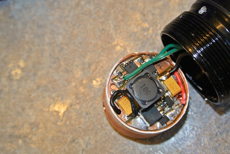
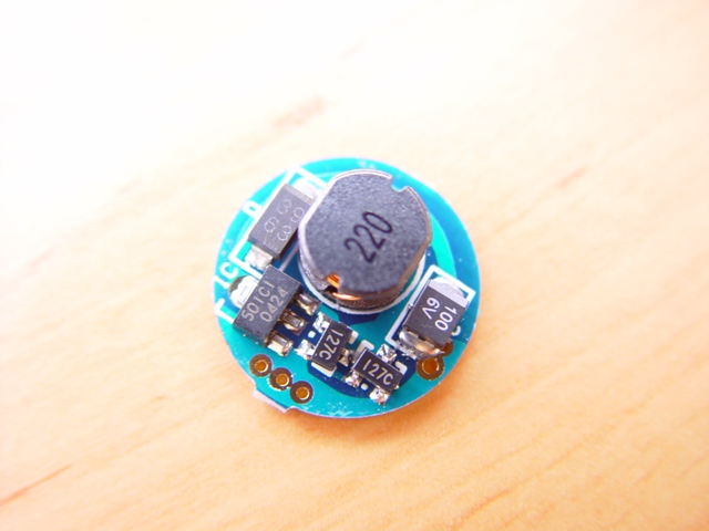
It seems that we have two FETs, two caps, one big inductor, and one controller.
very interesting build for sure
Too bad there isn’t a .brd file out there for it
Man I wish I had my old 2C Lamdalights low voltage input Mag. From what I recall it did pull a lot of amps from just 2 NiMH cells to feed the XML 3A or so. Was totally worth it, but pretty much dedicated to NiMH C cells due to high current.
Ventureblood I have a perfect Varapower direct drive switch I can let you have for FREE. You just gotta re-wire the switch to the board and off you go. I will PM you the details.
bigC
That would be fine with me. Once I have clear photos, measurements, and diagrams I can pass it along to whoever. I don’t have a need for an original Lambda Lights Varapower driver to keep.
That said, would there be more interest in a Varapower style driver which also had Low Voltage Protection?
I would think having that option was a nice feature. Since most high powered lights these days are li-ion.
My only real hang up with this driver is that millipede for a micro. I have no way of flashlight that beast, I'll probly just kick someone else a few bucks to program them for me.
I doubt this will help much but I found what I think is another picture of the 2 cell driver in this thread (hard to read anything in the pic). Near the bottom of pg 1.
http://flashlightnews.net/forum/index.php?topic=2477.0
lawallac,
If your interested in doing this
vob, the “millipede” is not an MCU, it’s what’s called a timer. You don’t program those. I guess they are considered a discrete logic component, although I’m not really sure if that’s the proper term. Anyway their function is not programmable, they are a building block for simple circuits. (555 timer IC - Wikipedia) If I were to implement LVP it would be with an MCU such as an Atmel ATtiny13A (which does need to be programmed).
As to what’s in the picture you referred to, it’s definitely not a 2-cell NiMH driver. It’s just a miniature version of the Varapower DD driver in your OP here.
Here is an update. I stuck this light in my make shift sphere to get a general idea of the results.
Turn on.......... 3222
30 seconds .....2878
1 min..............2718
2 min..............2552
3 min..............2241
I have to say I am quite impressed with this. Less than a 400 lumen drop from turn on to the 30 second mark, and a steady output even minutes into the test. At 8.3 amp I was expecting the drop from turn on to 30 seconds to be more than that. I guess there really is something to say for a large mass of copper.
I double checked to see if there was really anything more to gain going above 6 amps because previous tests on a smaller heat sink had indicated there was not much. At the 1 minute mark at 6 amps the light tested at 2224 so the 2.3 amps of extra current are yielding almost 500 extra lumens.
Hey, guess who just got an Email from Lambda. Yep, thats right. His sister No wait it was me!
He said that the max for this driver is actually 16V at 30A. WOW huh...
I sent him everyone's best wishes from BLF and CPF and told him how much we all miss him, and that the praises of his work still ring though our hallways..
Sorry for taking so long to get some pictures. But here you go. Glad you were able to get ahold of Kevin. I had emailed and didn’t hear anything back, glad he’s doin alright.

Lance
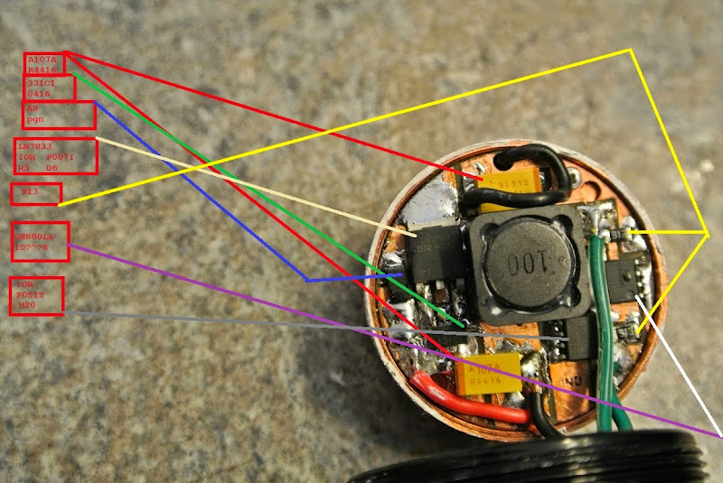
Thanks lawallac! Would it be possible for you to post the top markings that are on the components?
The two small black resistors are easily legible, as are the two large yellow capacitors. The large inductor is also clearly marked. What’s left is:
I’ve had some difficulty reading the components but here is what I make of it.
Good work lawallac, thanks!
I think I’ll have to bow out of attempting to clone this boost driver. Maybe I could ask Lambda for help understanding it if he’s willing. Not right now though.
No pot on this light. I don’t know if you had a chance to read through the thread Here , but he did mention difficulty in finding a FET that operated in the 2.4 voltage range. I will have to also peak inside the 2c versions.
Hmm, it’s starting to come together now. A little.
I’ve only skimmed the first page of that thread once or twice. At your suggestion I read the entire thing. Lambda doesn’t say that it’s voltage-controlled, but it is. 331C1 is a voltage controlled (CV) boost controller for 3.3v. I have been unable to find a datasheet, but 501C1 also exists (5v instead of 3.3v). Here is a clear photo of 501C1 from this thread on elektroda.pl. I see some more discussion on 501C1 over in this thread on the same forum.
Voltage controlled seems to be able to work acceptably, at least in some cases. DerWitchel also used CV in a driver (step-down though) for SST50/SST90.
In this case we’d see a little lower current on XM-L2 or a very low (<2A) current on XP-G2, based on djozz’s charts (post #51). Of course MT-G2 or strings of LEDs are both completely out of the picture, but that was really true anyway on 2s1p NiMH - regardless of driver selection!
It would still be worthwhile to me to find out exactly how this driver operates, but I don’t think that actually cloning it will produce great results.
Nice detective work wight. What your doing is black magic to me. 
We’d be in pretty good shape if it wasn’t black magic to me too, eh?! ![]()
Looks like the Russians have some different thinking on the subject of those boost controllers. Somebody over on radiokot.ru is saying that it looks like MC33463H in an SOT89 package. Another says ELM92501C-N (well, ELM92xxxx) in the SOT89 package.
The Polish folks thought that it was it was SOT223, but I’d been assuming SOT89. SOT89 has a tab which is flat and connects back to pin2 (same package as our 7135’s). I don’t know much about it, but it looks like SOT223 has a tab that comes out and then bends down - I’d say the pictures make it clear that that is not what we’ve got here. So we’ve got SOT89!
Moving on, the difference between the two current proposals is really just the location of Vout vs GND. They are transposed between the two components. Oops. Looks like the ELM product is only available with an internal FET, we need one with an external FET. MC33463H–XXLT1 still fits the bill I think!
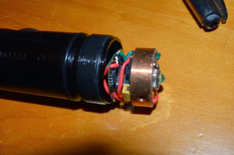
Here is what is inside of a 2C. Tight quarters in there!
I have 2 of these 2Cs. In this one Kevin made me a nice adapter to run an 18650.
