Eh, it’s actually a 27 ohm resistor (27 + zero zero’s is what the marking means). I think many of us make that mistake on a regular basis. Someone else just mentioned the same problem in a PM to me and I know it happens to me. (EDIT: and it definitely happened to me this time :laughing:
IOW that’s definitely the PWM pin. 27 ohms doesn’t matter one way or the other, you can solder your PWM wire wherever is convenient.
Great! Thanks for the help! I'm actually working on this right now. This is extremely difficult work for me and I might have to postpone it because I have other chores I need to get to.
Thanks wight! I’m in deep water without a vest here so it’s nice to have back up. When the FET is removed it should be obvious which is the pwm trace I was just trying to see if I was seeing things correctly first. I mentioned above that the resistor might not be needed for the slave mod. Thanks for the correction on the “0”.
Remember Garry, you don’t need to bring + power to the slave. Just the pwm signal, led-, and gnd. The last two will carry the full current so decent wires (awg24 or better for 3A).
Attach LED - to the 7135 based driver in the normal place
Add a heavy jumper wire for GND between the existing driver and the 7135 based driver.
Add a PWM connection between the existing driver and the 7135 based driver (it goes to the righthand pin on a 7135 when the tab is away from you). EDIT: You may get the PWM from the FET’s gate pin if you want.
So no connection for "Led+" coming in/out of the 105c? I've already attached it. And in fact I used the existing wire that came with the 105c as the "PWM" line as I couldn't get my 20ga attached (too big). Not sure what gauge these stock wires are. Anyone know off hand?
I forgot to mention that in my list. Small wires are fine for the PWM lead, no harm there. I don’t know what AWG the stock wires are, but they are fine for PWM.
No LED+ is necessary coming in/out of the 105c. It’s fine to use it, but all the 105c does is pass BAT+ directly to LED+ so it’s just extra connections and resistance. Not a big deal.
Side note: Note that while I’m very confident that you can get away with leaving the FET in place, eventually if you hook enough stuff up to an output pin of an MCU, whether that stuff is being used or not, the MCU will struggle to send out a strong enough PWM signal.
I'll remove the FET. I also got the Attiny13a removed too (that was tough!). I've not got all 22ga wire installed ready to mount to the existing driver. I even piggybacked another 7135 My first attempt at that ever! And I found that to be MUCH easier than attaching these darn wires! Just hope I didn't burn up any of the 7135s.
Im gonna have to quit for now. Thanks for the help!
FWIW, and I don’t do as many of these as others, I’ve never burned up a 7135 or had a “bad” one that I noticed. I’ve torn legs off of them several times, but it’s always been pretty obvious that I had physically damaged the thing.
Well I couldn't leave it alone, so it's connected!
Best at pic I can post until I get a chance to upload my high res macros. Not too bad of a job! Now I hope it works! Wait - let me test quick. Well it works, however I'm getting 2.35A measured in each mode (it still ramps down then back up between modes) with 2 unprotected cells in parallel at 3.99v. Ugh! Why'd I lose mode levels?
Ill probably post high res pics Monday. I'm done for now.
I took a closer look at the stock driver. It appears to be setup for current sensing after all. It’s probably still just doing PWM to the FET and using an RC circuit to smooth the sense voltage out.
so err, sorry! If I’m correct I’d say that this is not really a common setup. I’m not sure that the best solution is not to re-assemble the driver and do a sense resistor mod. EDIT: hold that thought. I’m taking an even closer look now. EDIT 2: OK, I’ll stand by that for now. Forgive me but this driver is only so interesting and I won’t stare at it all day. It looks like what I wrote in strike-through text may be the case.
Hmm, I’m not making much sense here. Why would you be limited to 2.4A if you bypass the sense resistors? They’d have zero voltage drop across them and thus the driver would attempt to run full blast. Maybe it never provides a 100% duty cycle no matter what. Your 105c is fully populated with 8x7135?
Anyway you can probably just use a normal FET like the 70N02 or AOD510 if you have those.
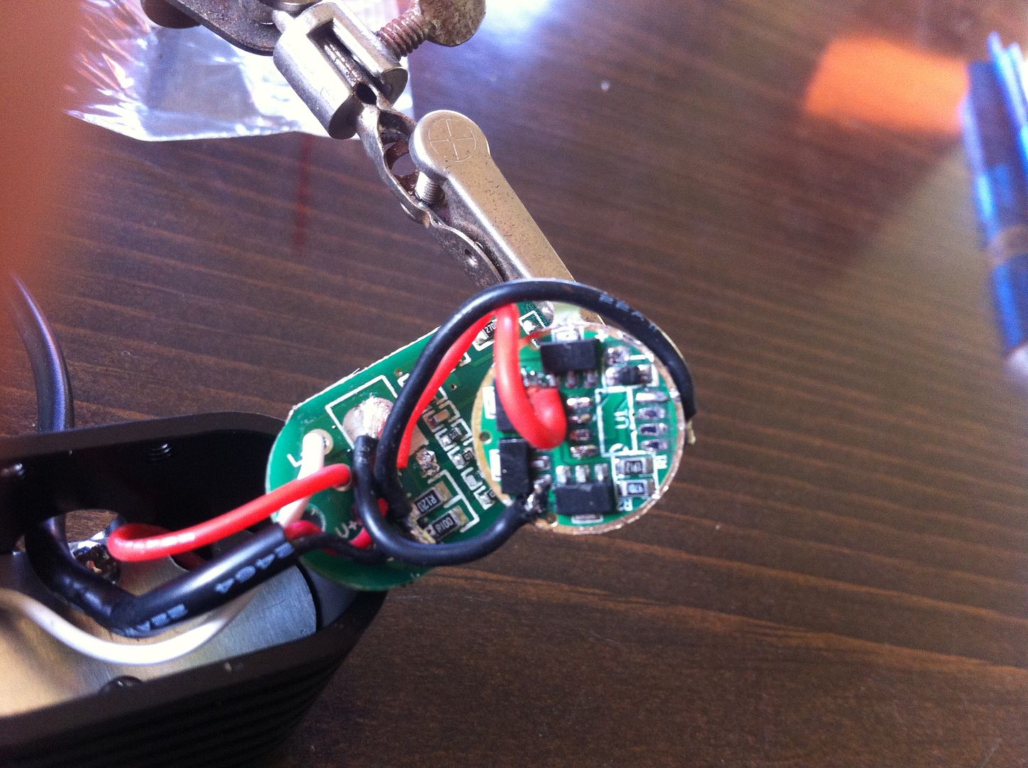
My 105c has 9x7135's now. Possible I burned some up? I don't have any FETs here at all on me. I did connect the GND directly to the incoming NEG lead (connected across those resistors where they connect to GND. The PWM wire is connected to FETs gate pad (lower left). LED- from new driver to to the FETs drain pad. I also checked for shorts on the 105c while wiring up.
If you would like to do an experiment let’s move the Nanjg 105c’s GND connection over to the right of the sense resistors and see if modes come back. I do not expect to see more current, but I do expect to see modes / levels.
Sorry for the mixup earlier. So it’s as I said: this driver appears to use current sensing through an RC circuit to do “CC” (not really) PWM. I’d drop an FET in and do the resistor mod to get the desired current.
How badly did you damage the FET when removing it? I’ve been doing some serious bending on one or two DPAK FETs over here and they aren’t dead yet…
I broke a corner of it off and one of the legs. Is there anyway to keep using the 105c with it (and get more output)? I know I could always just use it as a contact board and run the light entirely off the 105c, but I'd have to wire another one up that still has the MCU attached.
And so those ARE current sense resistors and NOT current limiting resistors? So going back to an FET would give me regulated output or not?
On a 7135 driver loss of modes sometimes means the pwm pin is pulled high (usually because the led + pad is shorted to the pwm pin closest to D1) but a momentary switch should not be able to interrupt that. Is there anything else on the trace we think is the pwm that might affect the signal ? If there’s unwanted capacitance there might it not prevent the 7135’s from turning off the way they should?
Either the maximum duty cycle the MCU (or whatever it is) will provide is <100% OR the 7135s just do not like something about the PWM signal (very high freq for example).
Those are current sense resistors but they are not used in a traditional way. This driver provides PWM output using an FET (like an East-092 driver) and varies the PWM to achieve a specified average current. That is not the same kind of output that a buck or linear driver generates. I’ve actually considered trying to do this but I decided that there must be some reason not to since nobody else was doing it. Kind of like the opposite of “if everyone else was jumping off of a bridge…” The average current is being regulated, this is not the same as what we normally refer to as regulated output.
You can probably grind the FET until that leg/pin can be soldered to. Using flux will probably help. Maybe carving with an X-ACTO knife could give better results than grinding/filing, depending on the situation.
I don’t think you have the ability to flash MCUs, but if you did you could use ToyKeeper’s STAR mod which features support for status LEDs. You’d just wire up the 105c to the status LEDs & their limiting resistors on the stock PCB.