I broke a corner of it off and one of the legs. Is there anyway to keep using the 105c with it (and get more output)? I know I could always just use it as a contact board and run the light entirely off the 105c, but I'd have to wire another one up that still has the MCU attached.
And so those ARE current sense resistors and NOT current limiting resistors? So going back to an FET would give me regulated output or not?
On a 7135 driver loss of modes sometimes means the pwm pin is pulled high (usually because the led + pad is shorted to the pwm pin closest to D1) but a momentary switch should not be able to interrupt that. Is there anything else on the trace we think is the pwm that might affect the signal ? If there’s unwanted capacitance there might it not prevent the 7135’s from turning off the way they should?
Either the maximum duty cycle the MCU (or whatever it is) will provide is <100% OR the 7135s just do not like something about the PWM signal (very high freq for example).
Those are current sense resistors but they are not used in a traditional way. This driver provides PWM output using an FET (like an East-092 driver) and varies the PWM to achieve a specified average current. That is not the same kind of output that a buck or linear driver generates. I’ve actually considered trying to do this but I decided that there must be some reason not to since nobody else was doing it. Kind of like the opposite of “if everyone else was jumping off of a bridge…” The average current is being regulated, this is not the same as what we normally refer to as regulated output.
You can probably grind the FET until that leg/pin can be soldered to. Using flux will probably help. Maybe carving with an X-ACTO knife could give better results than grinding/filing, depending on the situation.
I don’t think you have the ability to flash MCUs, but if you did you could use ToyKeeper’s STAR mod which features support for status LEDs. You’d just wire up the 105c to the status LEDs & their limiting resistors on the stock PCB.
Any decent DPAK FET which we’d use on a regular DD driver should work, AOD510 included.
RMM sells singles of IRFR3711ZTRPBF, that should be fine and I think it’s the cheapest option if you just want to purchase a single unit. Should be <$4 shipped.
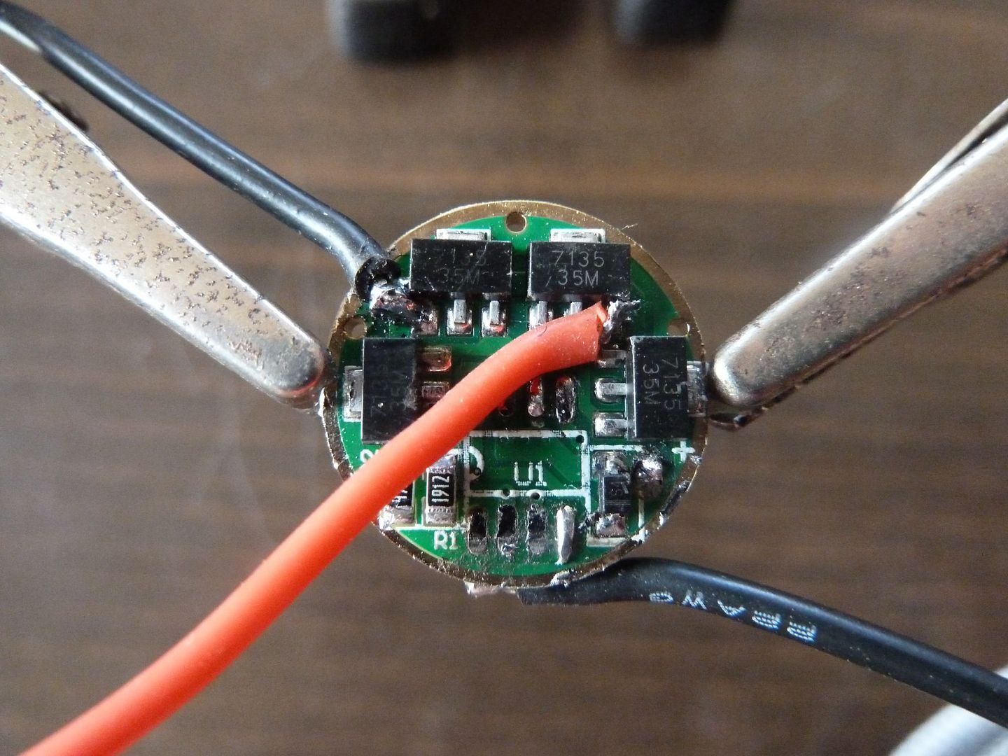
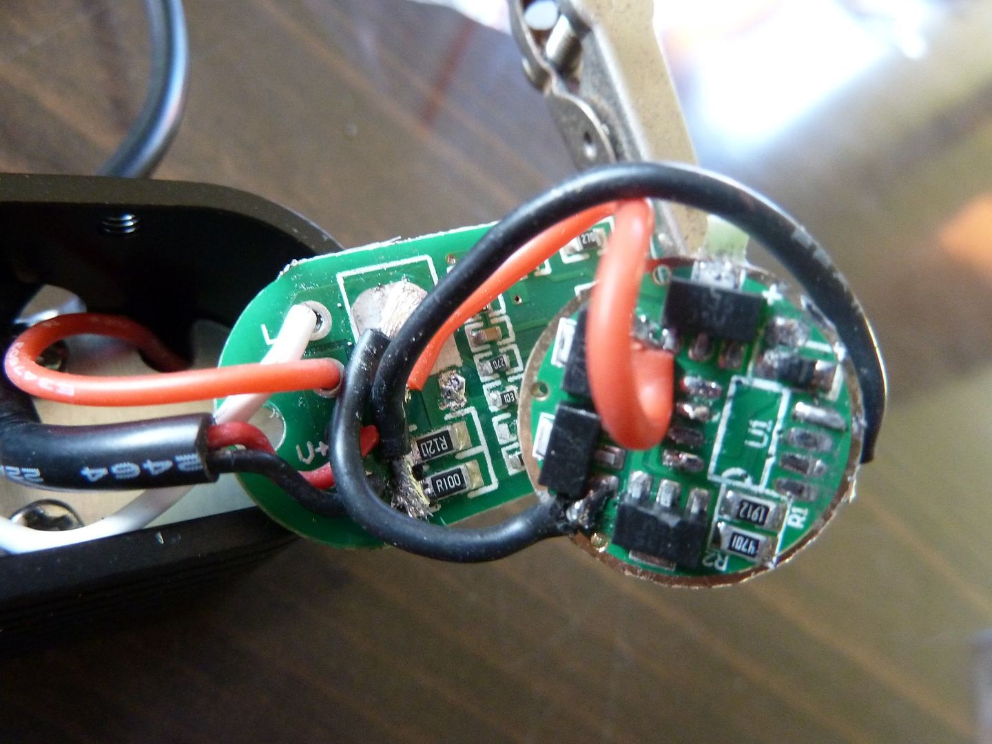
I've ordered 2 FETs from Mountain (along with other parts to keep on hand). In the meantime, here are those higher res. photos I promised:
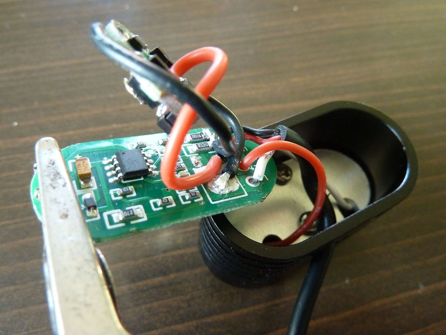
My final driver wiring after changing over to 22ga wires and removing the + wire (the PWM wire is the red):
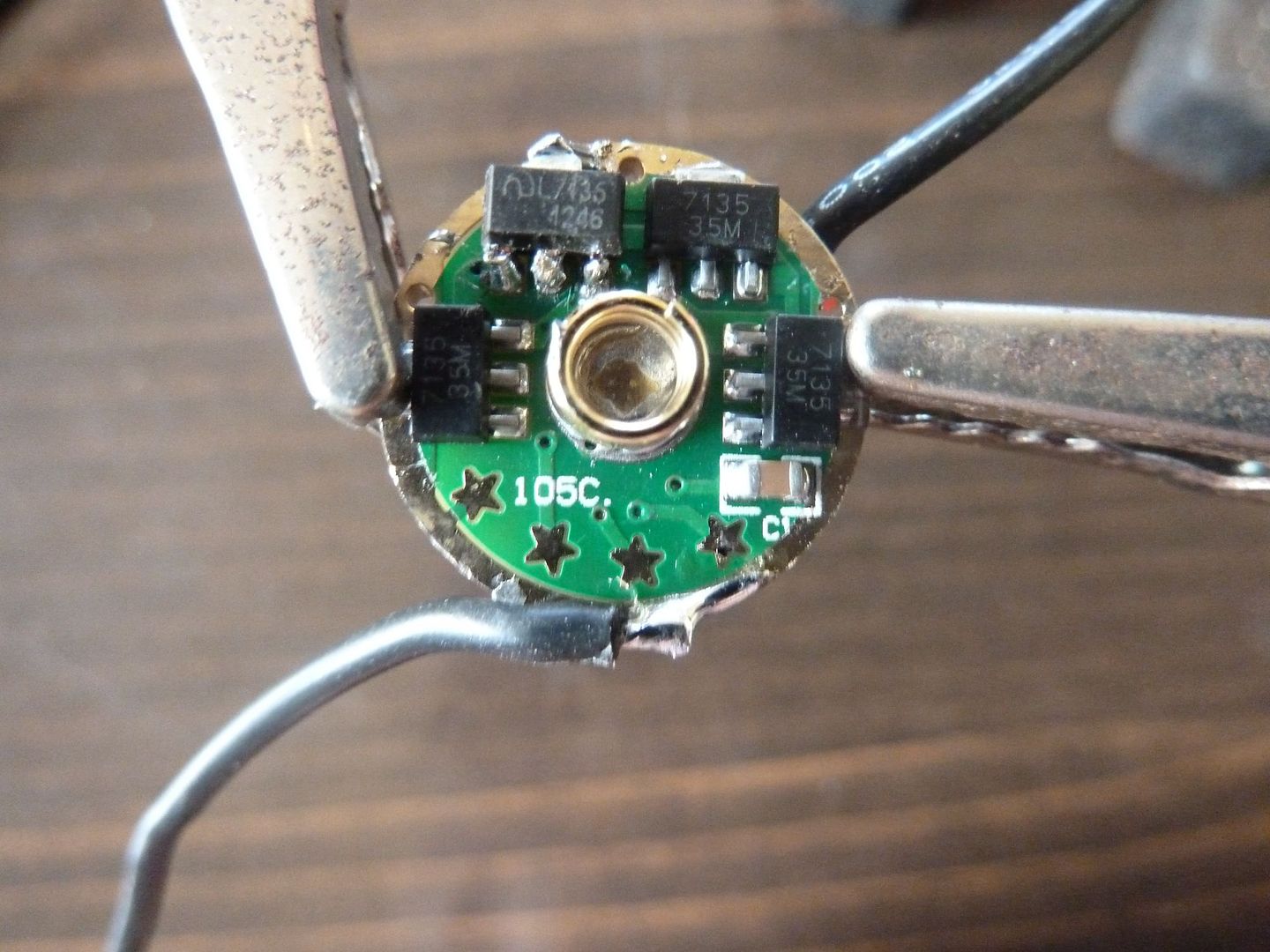
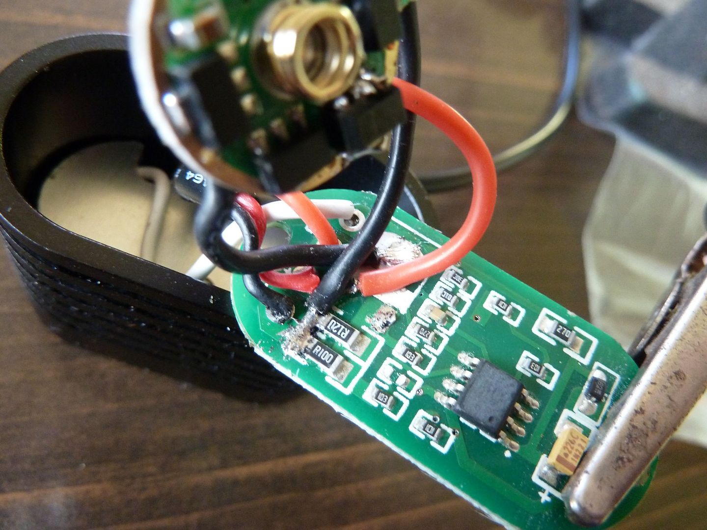
Ground Wire on the Back Side Due to Thicker Area to Attach (and my stacked 7135):
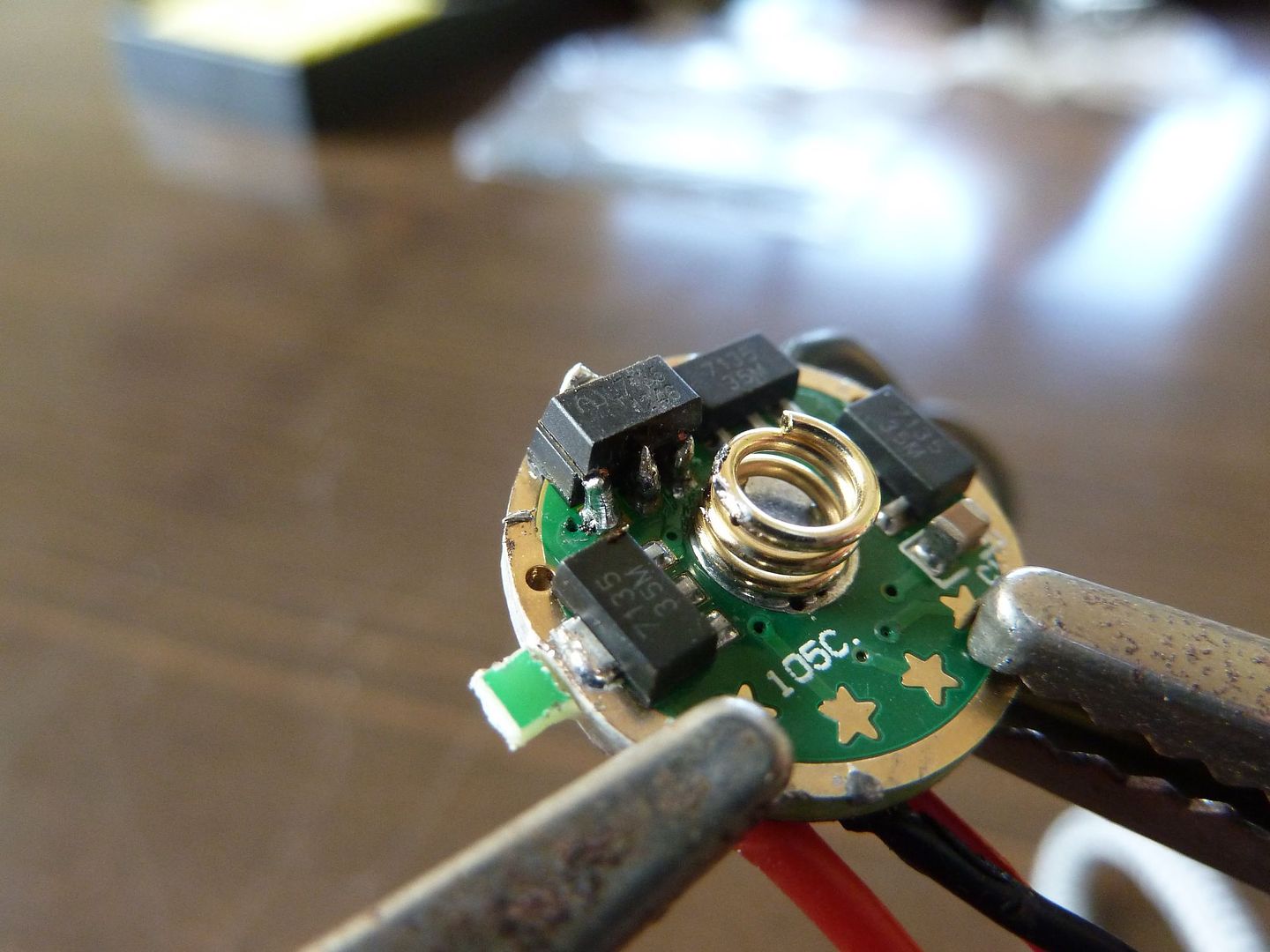
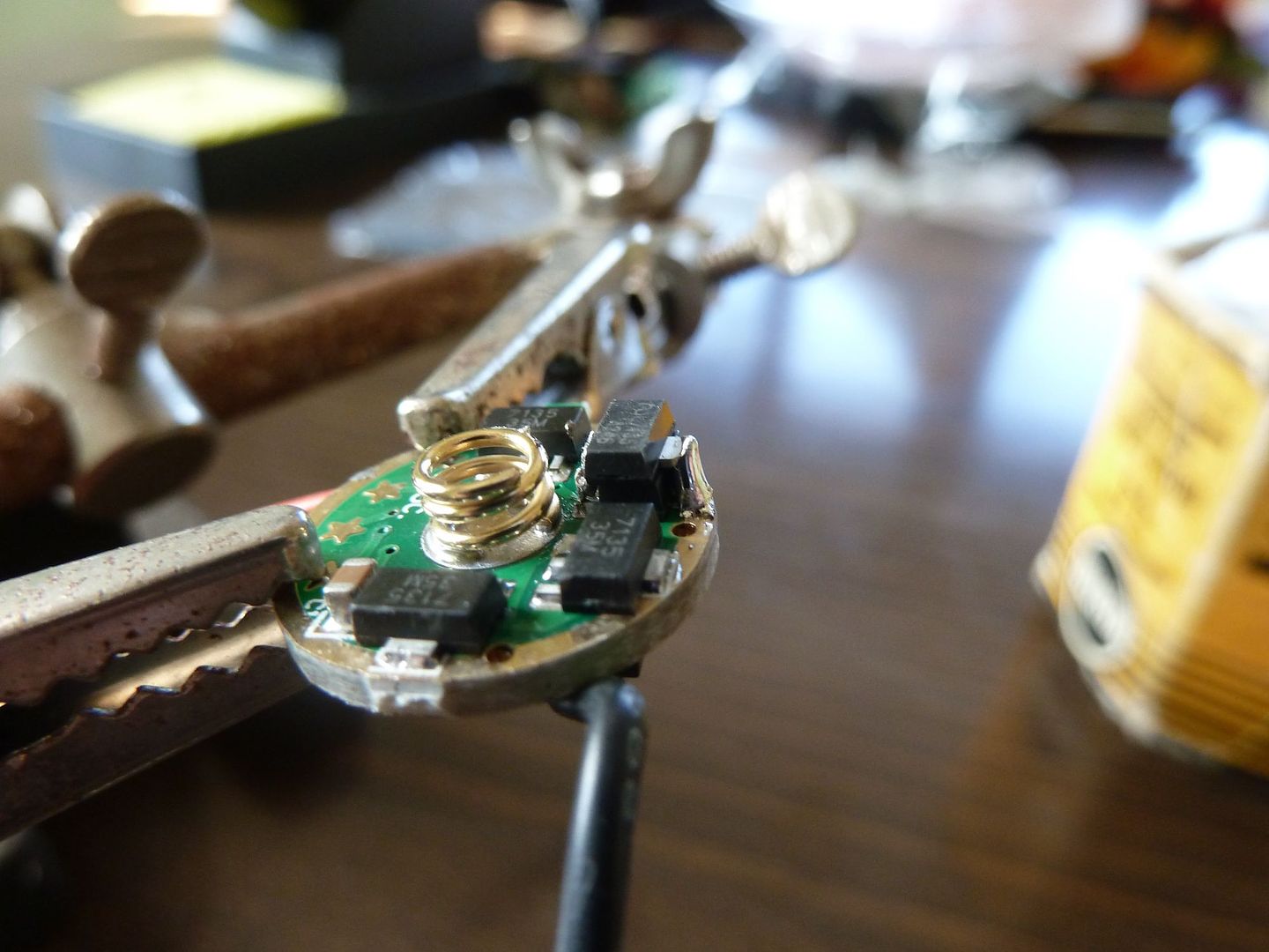
Closeups of my stacked 7135;
Few views of being wired up to the main driver board with FET removed:
Really tough to show the wiring with so much in the way! And those photos were prior to me moving the ground wire to the other side of the sense resistors. This was the wiring that gave me no modes.
I'll post back when I get the FET and get it remounted.
Well it was sweet until it didn't work (you read that part, right?)! It was good practice though. And as I stated earlier, that was my first attempt at stacking 7135's and I found that to be a lot easier than attaching those darn 22ga wires! I never had that slave board fully functional to see if I ended up with the proper current level (i.e. that I didn't burn up any 7135s).
I tell you what though, I am enjoying the quality of photos I am getting out of a camera that I only paid $39 for!
Poor Garry was led astray by a mad duck. The wiring looks exactly the way it should but unfortunately I was mistaken about how simple the swap would be. My bad. Once again, knowing a little will get you into more trouble than knowing nothing.
True but you still learn more from mistakes than you do from things you already know. In a situation where failure is not an option kiss is more appropriate but not for something like this where you can go back to square one with little risk.
. . . I don’t think you have the ability to flash MCUs, but if you did you could use ToyKeeper’s STAR mod which features support for status LEDs. You’d just wire up the 105c to the status LEDs & their limiting resistors on the stock PCB.
Do you know which modified version of STAR has this support? I searched for discussion on the topic, but didn't find any.
Ok here are my measurements at 4.2v battery pack (2 cells parallel @ 4.01v)
off: 0.011A
low: 0.98A
Med:1.30A
High: 1.75A
Now meter in line with LED wires:
off: 0.000A
low: 0.81A
med: 1.33A
high: 1.81A
So I guess my LED measurements are higher because my battery pack wiring & connectors (maybe just my connectors I add to get inline measurements) are adding some resistance. Anyway, I'm pretty much back to stock output. What resistors would I stack / replace? Think my goal was about 3A on high (1.5A per emitter). I know I have R120's and think I have R500's. I have others but I'd have to look.
By the way, I'm correct that the 1.75A I measure gets cut in half for "per emitter" current, right?