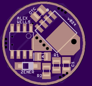
I have updated this board with a thicker GND ring on top and new, more legible silkscreen for D1. I thnk I also tweaked the copper pour for LED- to flow slightly better into the FET pad - a purely aesthetic change. These changes are based on changes I implemented for the A17DD-SO8 driver.
https://oshpark.com/shared_projects/pcTBBHOv
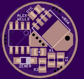
When I came over here to post the v024 update I saw Werner’s post #61 again. That got me thinking, so I updated the driver to v026.
Werner is using only 3x7135, controlled by 2 pins on the ATtiny. One 7135 connects to Pin5. The other two 7135’s connect to Pin3. In v024 and earlier this makes the bottom of the board lopsided because all of those 7135 positions are next to each other.
To combat this I made it easy to drive all 5 of the non-PWM 7135 positions from Pin3. I moved the via next to Pin1 a little bit to make the trace easy to cut on top of the board (so it’s not visible after the build). I also ran a trace from the via over to a solder jumper at the pad for Pin3. You should be able to place a small bit of solder there and still operate a clip. If the jumper requires too much solder and makes using an SOIC clip a pain I’ll tweak it.
Once you’ve cut the trace and soldered the jumper you can then run 3x7135 like Werner did, but in a nice triangle configuration.


https://oshpark.com/shared_projects/7FzwbScm
There appears to be an error in the OSH Park render such that the BLF text is spun around. I’ve emailed support about this. It works fine in GERBV. (No it doesn’t. What was I thinking? I’ll upload a version with the text in the correct orientation!)
Is there firmware available yet?
I wasn’t brave enough yet, because of the fuse thing. And I was to lazy to build a fuse resetter…
so there is just the above posted version which works but without support for the 3x7135 group, but it doesn’t ruin the tiny for sure.
Thanks Werner, appreciate the work being done on this. Unlike the LD-1 this one could run an MT-G2.
Technically I think you can run the dual-PWM STAR firmware with these, just like RMM’s Moonlight Special. It’ll only take advantage of a single 7135, but you should be able to achieve consistent, low, moon modes. AFAIK that should work for ontime and offtime clicky builds.
Werner’s momentary code from post #61 should work; Werner has tested it but I have not. That code is for controlling 3x7135s and can be easily adapted for 2 as well with the old hardware. With the new hardware Werner’s code can be adapted to run as many as you want but they’ll still be controlled together (for example 1 with PWM and the other 5 as on/off together).
I just sat down and read through some of these revisions and wow! Pretty sure it’s just me…
Oh, also I don’t think Werner made it clear but that momentary firmware could also be used for one-shot programming of ATtiny13A’s with our normal USBASP programmer. If you know your modes configuration it seems to me that Werner’s firmware is good to go… you just can’t reprogram.
I probably make it sound more complex than it really is. There’s really nothing super complicated about it the design, it just turns different quantities of 7135 on and off, plus has an FET to turn on and off.
Hi guys, excellent work as usual! ![]() Im just wondering wouldn’t that be excellent driver for one XM-L2 if we put 8 7135’s and use Attiny13a to control it like 1x7135, 1+3x7135 and 1+3+4x7135, so then we have quite nice efficiency on all modes right? Maybe this 1x7135 should go with PWM if possible. Next we need someone who can draw this driver to Oshphark and little more code. No need for FET, we could stack 7135’s if more power needed right? What do you think?
Im just wondering wouldn’t that be excellent driver for one XM-L2 if we put 8 7135’s and use Attiny13a to control it like 1x7135, 1+3x7135 and 1+3+4x7135, so then we have quite nice efficiency on all modes right? Maybe this 1x7135 should go with PWM if possible. Next we need someone who can draw this driver to Oshphark and little more code. No need for FET, we could stack 7135’s if more power needed right? What do you think?
Thanks!
Stacked 7135’s can’t do what the FET can.
Also, this driver is on OSH Park.
Maybe after the firmware is solid for this one I will make an 8x7135 driver with no FET.
Pilotpptk once made this but it got never released…
There is a very easy to build fuse resetter that I have tested it works. www.simpleavr.com/avr/hvsp-fuse-resetter
I look forward to a day when this has established firmware…
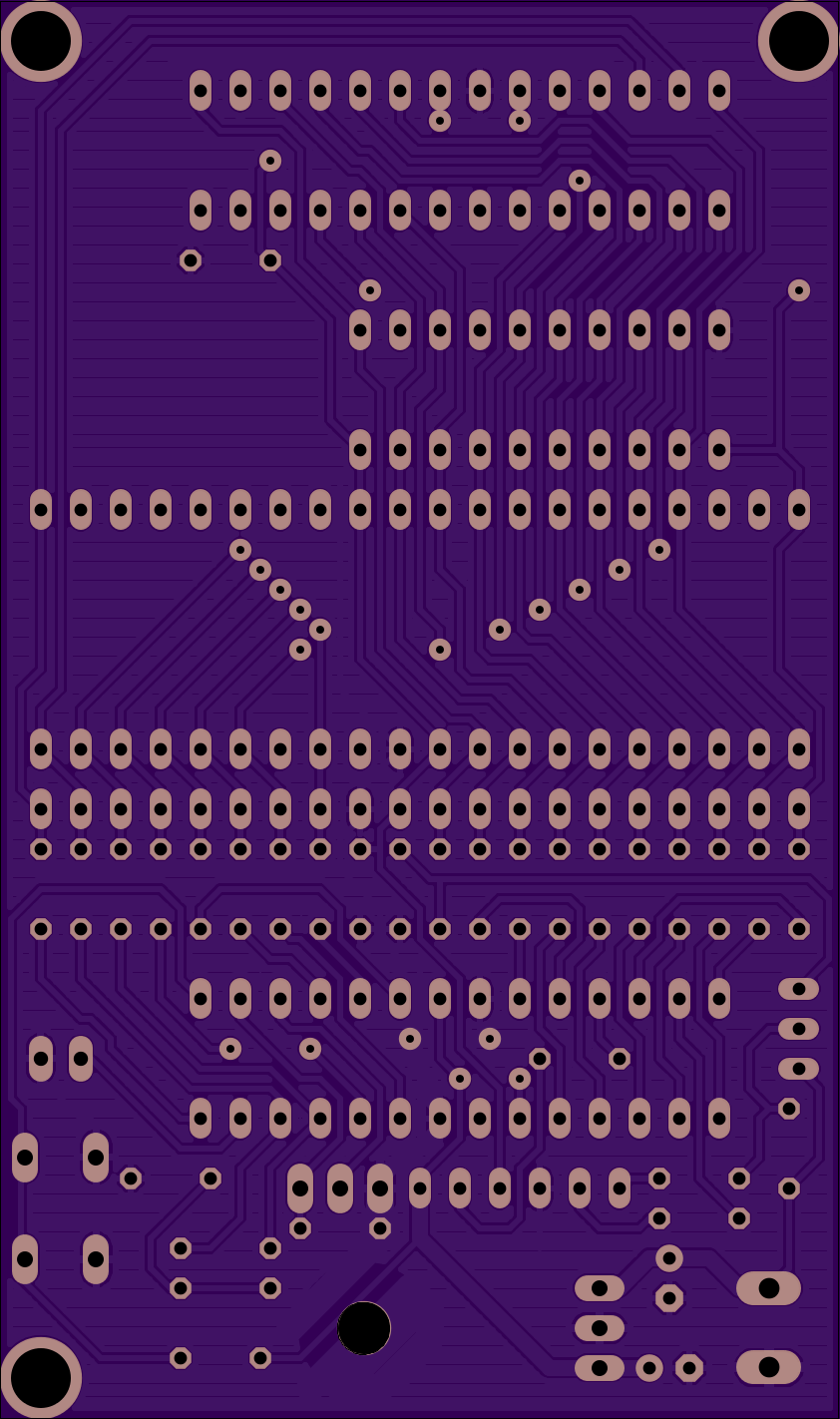
I took this guys version and cut it down smaller, only need the adapter board for the ATtiny13
http://mdiy.pl/atmega-fusebit-doctor-hvpp/?lang=en
Atmega fusebit doctor (HVPP+HVSP) Short board Warhawk’s tweak
adapter_HVSP WarHawk’s tweak
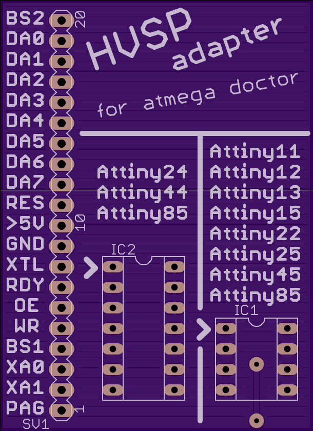
Can cut everything off above DA7 for even smaller board
I think on the guys later revisions, he fixed the problem with one of the traces on his board that got cut by a drill (this is his unmodified full size board [other than me tweaking and filling the polygon pours between traces], look at the very bottom in the center, the power trace runs right thru a drill hit) [I did mention it to him in his thread, I think he fixed it, but my tweak I re-routed it for the “short board”]
Could we just drop one of the groups of 7135 chips? That would make things quite a bit easier… Only four pins are freely assignable without consequence, and the driver tries to do I/O for at least five independent components.
So, it would then have:
- PWM1 = FET
- PWM2 = 1x7135
- I/O A = Nx7135
- I/O B = off-time cap or e-switch
And no need for any new flashing hardware.
Adding a PWM-controllable 7135 chip to a FET driver is a huge upgrade which addresses most of the shortcomings of a FET. Adding a second set of 7135 chips, minus the PWM, helps make a medium mode more efficient but otherwise has limited usefulness. A third set has even more diminishing returns, and comes at a pretty high cost (either requires overlapping pin functions and harder flashing, or requires dropping the off-time/switch pin).
Personally, I’d drop the second set of 7135 chips too, and make room for another sensor or something. One FET, one 7135, and two pins assignable for switch, off-time cap, or thermometer.
I don’t see big problems with the fuse resetting. If once a working firmware is available we just need to flash it once. I seldom change my firmware, I also never use the stars, I just make it like I want it to be and voila…
My arduino nano board arrived today, I will try to add a transistor and some resistors in the next days…a nano costs less than 4$.
I will try this:
http://homepage.hispeed.ch/peterfleury/avr-hvsp-fuse-restore.html
—-
Warhawk a PCB for fuse resetting is cool, it looks a bit big. How are the dimensions?
Adding a wire to my soic clip and using a “fake ISP” socket to reset the fuses, seems to be the best way for resetting assembled drivers, I hope that works because there is 12V on the reset pin!!!
Freely assignable without consequence: you mean 5 pins, not 4? 8-3=5, or am I ignoring something again? You were referring to the pins that are left after we establish a voltage monitoring pin.
As far as the groups… I’d say the FET and the first 7135 get you repeatable Moon mode with PWM and maybe a small Low without PWM. The second set gets you up to a total of 2.28A for your regular usage mode, PWM free - so no buzz. With 6 spaces and the option for .35 or .38A components you’ve got a pretty granular ability to setup Medium/High for PWM free operation. With this 7135+FET driver I do agree that any extra sets of 7135 beyond set 1 and 2 are gravy; eg the driver should work acceptably without 4 outputs.
Note that v026 is posted above in post #63 and allows for the FET + 1*7135 + 1-to-5*7135 setup, allowing you to stop using Pin1 and still use all 6 placements if desired. If a temp sensor is desired Pin1 can be fused for use and setup as an ADC. [EDIT: and in that case you’d cut the trace and solder the temp sensor lead directly to Pin1, which is fine because you’d have to remove the MCU from the PCB for any changes anyway since it would require HVSP.]
I agree with the rest, but I don’t think HVSP is intended for in-circuit programming. If Pin1 is attached to Vdd on a 7135 then HVSP will take the 7135 out of spec: there will be 12v on Vdd and 0v on GND, I expect the 7135 to fry.
Since an FET is the least efficient on pwm why not have two sets of pwm 7135’s and the FET fixed (on or off only) and just use it for turbo. With 6 x 7135 that would give up to 2A on pwm and a genuine jump to turbo.
I like that, and the FET can probably take 12v on gate too IIRC (so maybe in-circuit HVSP?), but that prevents smooth turbo ramp down.
The issue is with using non-vector text, what “vector” is is text that each point / line corresponds to an exact coordinate so it will always be rendered / printed EXACTLY as it appears on the screen. Trying to use proportional text you will end up with the text slightly different, either shifted or miss-alligned or even contorted out of shape. I ALWAYS use vector. To many time’s I had boards that came with the text moved half way off the board or moved up to a copper area (and thus not printed at all) or some other way messed up, not once since switching to vector (and also centering it on the point) have I had a render / printing issue.
I cant tell on my phone screen, its to small, maybe it is but if not you really should use vector text.