Any decent DPAK FET which we’d use on a regular DD driver should work, AOD510 included.
RMM sells singles of IRFR3711ZTRPBF, that should be fine and I think it’s the cheapest option if you just want to purchase a single unit. Should be <$4 shipped.
I've ordered 2 FETs from Mountain (along with other parts to keep on hand). In the meantime, here are those higher res. photos I promised:
My final driver wiring after changing over to 22ga wires and removing the + wire (the PWM wire is the red):
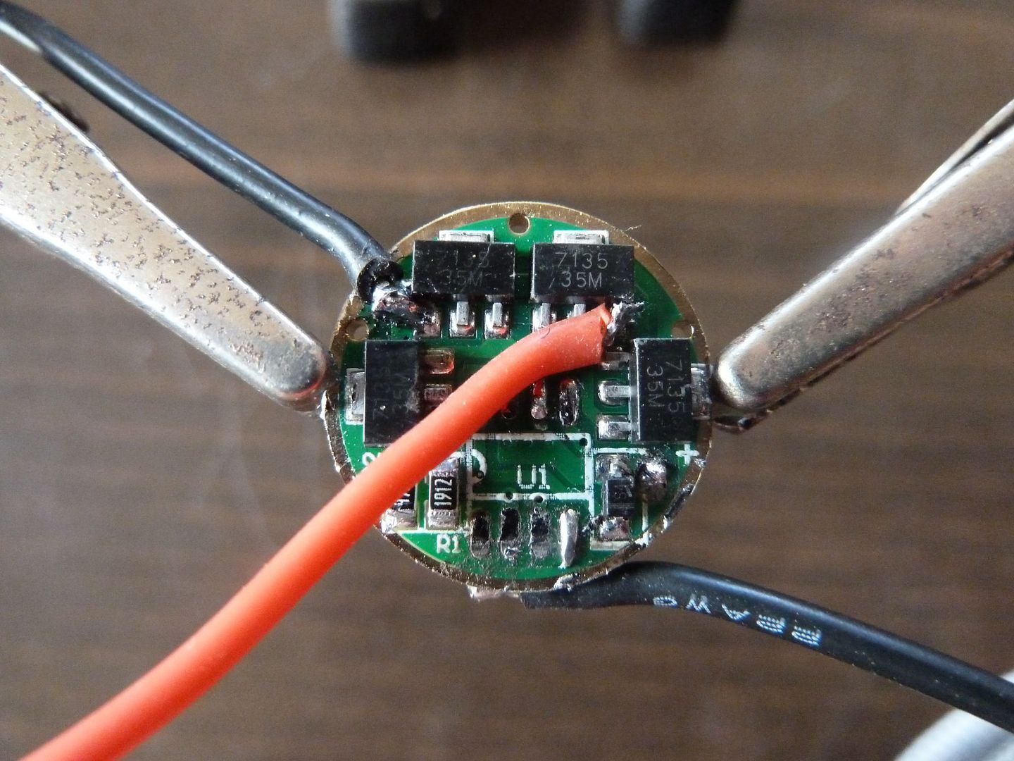
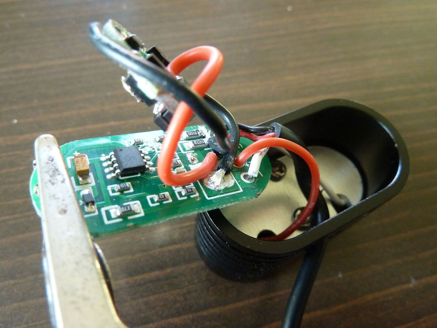
Ground Wire on the Back Side Due to Thicker Area to Attach (and my stacked 7135):
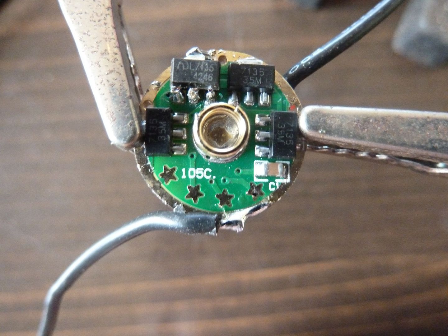
Closeups of my stacked 7135;
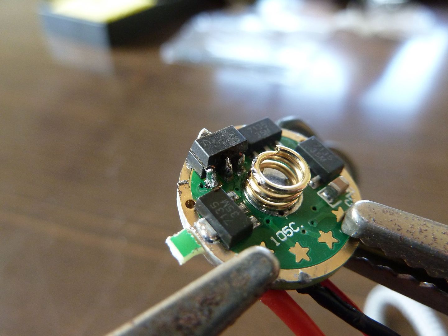
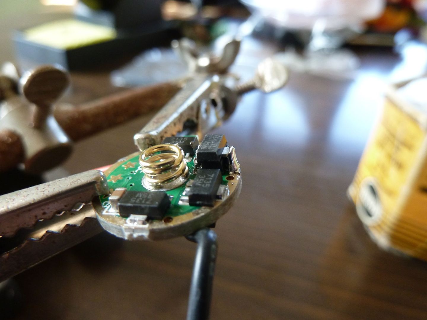
Few views of being wired up to the main driver board with FET removed:
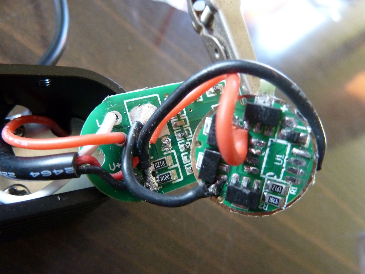
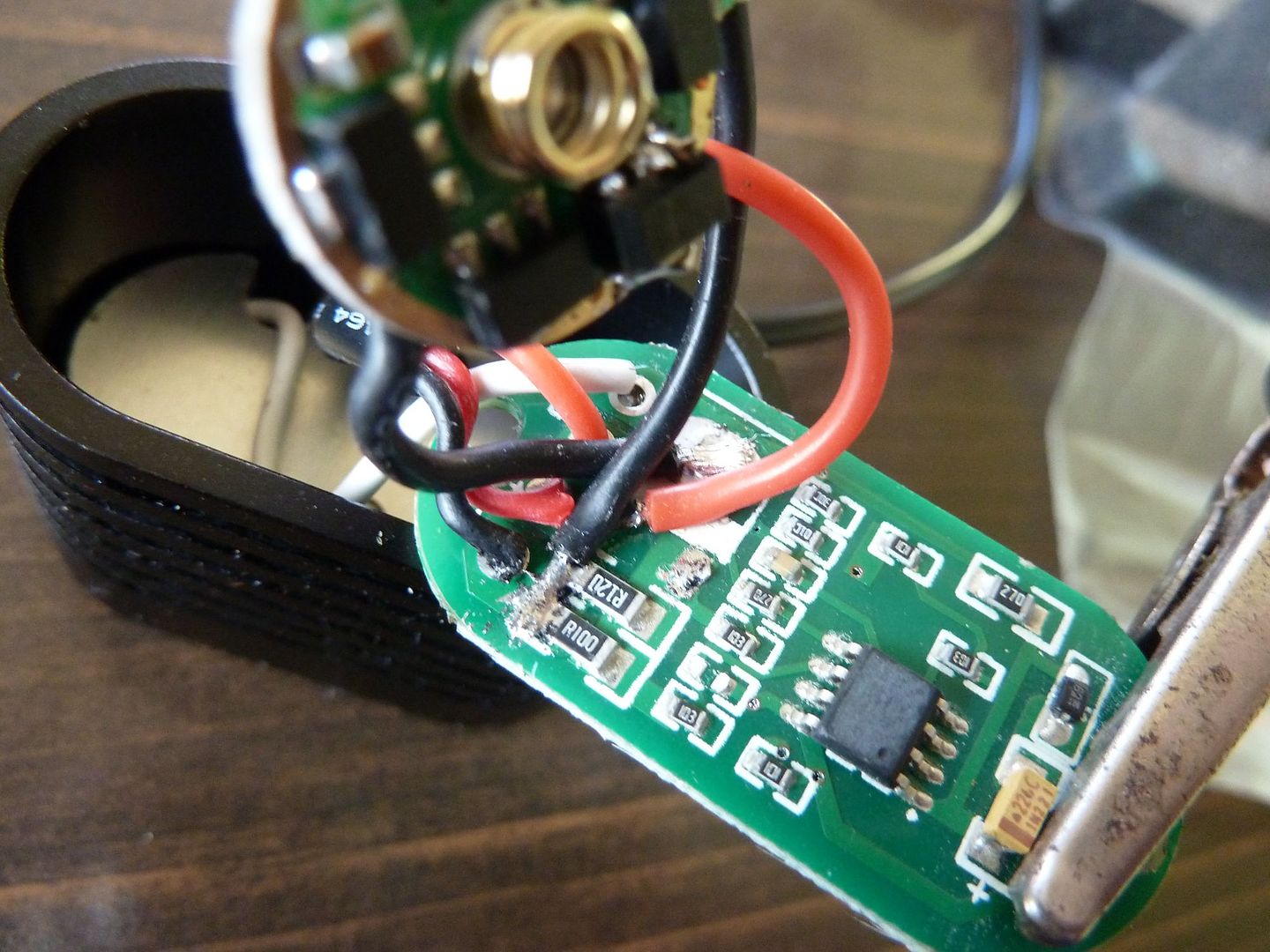
Really tough to show the wiring with so much in the way! And those photos were prior to me moving the ground wire to the other side of the sense resistors. This was the wiring that gave me no modes.
I'll post back when I get the FET and get it remounted.
-Garry
^ Sweet driver mod you got going there. That 7135 stack is just showing off. So many of us wish we could stack those that well.
Well it was sweet until it didn't work (you read that part, right?)! It was good practice though. And as I stated earlier, that was my first attempt at stacking 7135's and I found that to be a lot easier than attaching those darn 22ga wires! I never had that slave board fully functional to see if I ended up with the proper current level (i.e. that I didn't burn up any 7135s).
I tell you what though, I am enjoying the quality of photos I am getting out of a camera that I only paid $39 for!
-Garry
LOL. OK, semi-sweet driver mod. Or, sweet looking driver mod. What it lacks in functionality, it makes up in personality.
Or, I4W likes pictures and skim reads a lot.
Sorry about it not working yet. Looking at the wiring, it looks like you have it connected properly.
Poor Garry was led astray by a mad duck. The wiring looks exactly the way it should but unfortunately I was mistaken about how simple the swap would be. My bad. Once again, knowing a little will get you into more trouble than knowing nothing.
The perpetrator did not act alone. ![]()
We’ll get garrybunk straight in the end.
…rewind to post #1 and do the sense resistor mod.
Lesson learned: KISS
True but you still learn more from mistakes than you do from things you already know. In a situation where failure is not an option kiss is more appropriate but not for something like this where you can go back to square one with little risk.
wight wrote:
. . . I don’t think you have the ability to flash MCUs, but if you did you could use ToyKeeper’s STAR mod which features support for status LEDs. You’d just wire up the 105c to the status LEDs & their limiting resistors on the stock PCB.
Do you know which modified version of STAR has this support? I searched for discussion on the topic, but didn't find any.
Yes. ![]() It’s the version discussed in comfychair’s Roche F6 Hacking thread.
It’s the version discussed in comfychair’s Roche F6 Hacking thread.
She may have implemented the status LEDs in one or more of her other firmwares, but I know that they are present in this one for Helios-’s Ferrero Rocher DD driver for the F6: http://bazaar.launchpad.net/~toykeeper/flashlight-firmware/trunk/files/head:/ToyKeeper/Ferrero_Rocher/
^ Didn't search that thread. Searched the OSH Park and STAR threads. Thank you. :)
Got the new FET from RMM mounted. Now I'm gonna power up and check currents from battery pack and at LED wires.

Cruddy cell phone pic.
-Garry
Ok here are my measurements at 4.2v battery pack (2 cells parallel @ 4.01v)
off: 0.011A
low: 0.98A
Med:1.30A
High: 1.75A
Now meter in line with LED wires:
off: 0.000A
low: 0.81A
med: 1.33A
high: 1.81A
So I guess my LED measurements are higher because my battery pack wiring & connectors (maybe just my connectors I add to get inline measurements) are adding some resistance. Anyway, I'm pretty much back to stock output. What resistors would I stack / replace? Think my goal was about 3A on high (1.5A per emitter). I know I have R120's and think I have R500's. I have others but I'd have to look.
By the way, I'm correct that the 1.75A I measure gets cut in half for "per emitter" current, right?
Thanks,
-Garry
Iout = Vref / Rsense
Vref = Iout * Rsense
Rsense = Vref / Iout
Therefore for 3A output you want something like 0.033 ohms for Rsense. Three R100’s would be good. Four R120’s is 0.03 ohms for ~3.3A output.
By the way, I’m correct that the 1.75A I measure gets cut in half for “per emitter” current, right? - Yes.
Thanks. I'll try the (4) R120's and then measure again.
-Garry
Ok, I pulled the R100 and stacked (3) R120's (left other R120 in place). My resistors are supposed to be 0805 size from FastTech and they are 1/2 the size of the ones on this driver. Does that seem right? Is it ok?
Anyway, current on the LED wire is now:
Low-1.32A
Med-1.80A
High-1.96A
I'm wondering now if the LED leads are too thin. Holding the lead up to 24awg wire I'd say its close to the same size, maybe a size smaller (26Awg?).
-Garry
Or could I have burned up a resistor? Or do the new Low & Med currents show the resistors are all good?
-Garry
It may be that the thing has a maximum duty cycle it will not exceed. The new Med/Low currents do seem to indicate that the resistor mod is having an effect. Just not the end result you want for some reason. ![]()
0805 sized sense resistors should be OK with 4 in parallel. They are quite small compared to 1206 sized ones, I prefer to use 1206 when I can. Assuming the 0805’s are good for 1/8-watt or greater, there should be no problem with dumping around 0.3w across 4 of them in parallel.
EDIT: no harm in replacing the leads.