I like that, and the FET can probably take 12v on gate too IIRC (so maybe in-circuit HVSP?), but that prevents smooth turbo ramp down.
The issue is with using non-vector text, what “vector” is is text that each point / line corresponds to an exact coordinate so it will always be rendered / printed EXACTLY as it appears on the screen. Trying to use proportional text you will end up with the text slightly different, either shifted or miss-alligned or even contorted out of shape. I ALWAYS use vector. To many time’s I had boards that came with the text moved half way off the board or moved up to a copper area (and thus not printed at all) or some other way messed up, not once since switching to vector (and also centering it on the point) have I had a render / printing issue.
I cant tell on my phone screen, its to small, maybe it is but if not you really should use vector text.
I use vector text so that I can control the stroke thickness.
The issue was just that I was mistaken. I checked my BRD and Gerber files and the OSH Park render and simply became confused. The text is rotated incorrectly, I will correct this in the next version.
there is only one way to find out I what happens if you power a 7135 with 12V…
I looked in the data sheets I have and some rate it for 10V max on Vdd, so with a bit tolerance and good luck it will work. Or you have to add a jumper pad to the circuit which needs to be bridged to power the 7135 on the resetpin…or I just cut the trace and bridge it afterwards.
I will try to build a resetter and test it in circuit in near future.
I have thought again about removing the tiny for resetting and with a hot air this is a breeze, so a fuse resetter with a smd pad for a tiny could work like the one Warhawks has in mind. Just desolder it press it on the pcb with a finger and voila…
The Atmega fusebit doctor (HVPP+HVSP) Short board Warhawk’s tweak
2 layer board of 2.10x1.79 inches (53.34x45.52 mm)
cost $18.80 per set of three.
The adapter_HVSP WarHawk’s tweak
2 layer board of 1.53x2.10 inches (38.76x53.34 mm).
cost $16.00 per set of three
I don’t have em shared, or have tested them either
Question, is the Teensy an Arduino compatible unit…they are $17 from OSHPark I believe
https://www.pjrc.com/teensy/teensy31.html
Interesting Why Teensy is Better Than Arduino-TechnoGumbo
I don’t think that’s the question. ![]() Not when we are picking up Arduino clones for <$5.
Not when we are picking up Arduino clones for <$5.
Interest has been expressed in not using Pin1 (Reset). There are not a lot of different pin configurations which make any kind of sense. Here’s what’s on my mind, please let me know if I’m missing something:
|
Pin 1 (Reset) |
Pin 3 (on/off) |
Pin 5 (PWM) |
Pin 6 (PWM) |
v029 trace config |
|
|
Current/Original |
3*7135 |
2*7135 |
FET |
1*7135 |
c+a |
|
alt Current (v026) |
n/c |
5*7135 |
FET |
1*7135 |
a |
|
proposed |
n/c |
FET |
5*7135 |
1*7135 |
b |
|
proposed |
n/c |
? |
? |
? |
? |
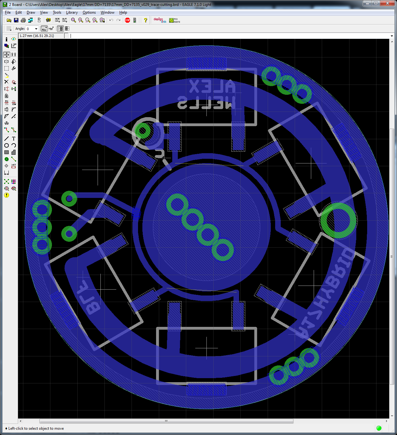
If anyone thinks it’s worth messing with for testing, I’ve devised a PCB which requires trace cutting before use but allows all 3 configurations (as a one-time setup option). I absolutely do not think that this is a great idea for most people building their own boards, as it is too confusing and trace-cutting in this location is basically one-way. This is really just intended as a semi-flexible test platform. Note that “c” is on the bottom and requires both cutting and a solder jumper. EDIT: “a”, “b”, and “c” all indicate CUTS which must be performed.

Wight, has low-voltage protection been designed into this driver?
Yes. Resistor values for one cell are 22k/4.7k 1%. I’ve found those values to be acceptable. For a lower-voltage activation of LVP some may want to tweak firmware values very slightly I think.
> wight and ck
> (and me) …. torn off ground rings …
> rufusbduck
> I like the idea of lots of gnd ring vias to anchor the copper, also on critical led+/- pads. I like having some of the gnd ring vias a bit larger in dia to allow for ground wires
Yes yes from the sidelines here. Anything that puts more copper through the board, especially along the edges where it can be press fit to make a decent connection for ground …
I’d guess this is where homemade drivers will excel — being willing to spend a bit more metal to make something people can fiddle with a few times without destroying it.
Now if you could solder the driver board right into a retaining ring so the whole thing would screw down into the pill ….
Ok if you don’t mind the emitter wires twisting in the process
I don’t think that the vias are as important as increasing the surface area that is covered with copper. In my experience: In only notice vias holding anything together once the copper layer is already lifted.
Not the same thing, but related: IIRC Solarforce uses a 16mm double-stacked driver which they solder into an adapter ring on the inside (eg during reflow I assume). this presses into a standard 17mm driver cavity. … again, assuming I recall correctly
That sound like a good way to get ground to 2 boards
Too bad I don’t have pics. GND is passed in the normal way (using a post/pin/peg between the two PCBs). Only the larger, bottom PCB is actually attached to the ring.
> if you don’t mind the emitter wires twisting
Yeah, I count the turns and pre-twist them the other way so they untwist as things screw together.
Extra wire, I know, but I need that just to get ahold of things to solder them.
Do you use tweezers to hold things?
:zipper_mouth_face: … And a good light.
Hi Alex, any progress on this?
Maybe he is waiting till STAR can control more outputs?
I think the FET+1 driver style has been getting most of the attention lately… it uses a single 7135 chip for modes from 0.1 lm to about 130 lm, and a FET for everything above that. So, the best of the highs and the best of the lows, and still pretty okay performance in the middle.
The extra 7135 chips on this driver would be useful for a medium mode or two, but it’s an awful lot of extra complexity just to improve efficiency on one or two middle modes.