I don’t think that’s the question. ![]() Not when we are picking up Arduino clones for <$5.
Not when we are picking up Arduino clones for <$5.
Interest has been expressed in not using Pin1 (Reset). There are not a lot of different pin configurations which make any kind of sense. Here’s what’s on my mind, please let me know if I’m missing something:
|
Pin 1 (Reset) |
Pin 3 (on/off) |
Pin 5 (PWM) |
Pin 6 (PWM) |
v029 trace config |
|
|
Current/Original |
3*7135 |
2*7135 |
FET |
1*7135 |
c+a |
|
alt Current (v026) |
n/c |
5*7135 |
FET |
1*7135 |
a |
|
proposed |
n/c |
FET |
5*7135 |
1*7135 |
b |
|
proposed |
n/c |
? |
? |
? |
? |
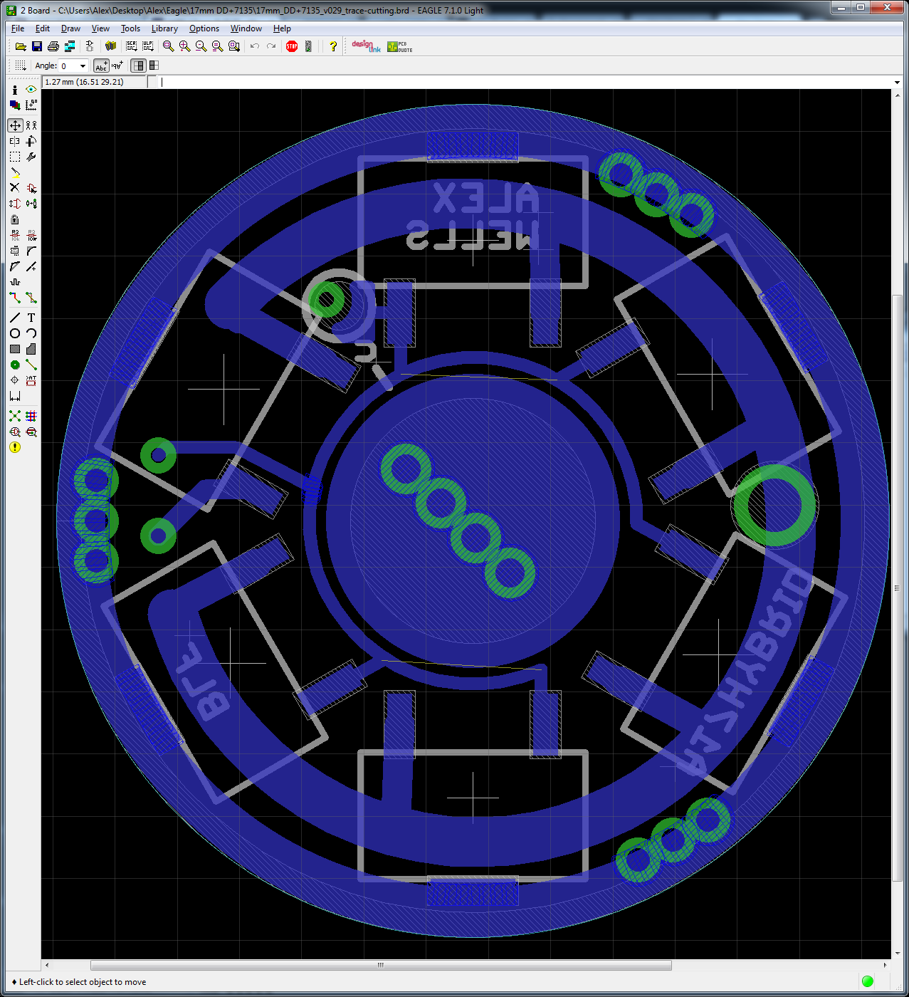
If anyone thinks it’s worth messing with for testing, I’ve devised a PCB which requires trace cutting before use but allows all 3 configurations (as a one-time setup option). I absolutely do not think that this is a great idea for most people building their own boards, as it is too confusing and trace-cutting in this location is basically one-way. This is really just intended as a semi-flexible test platform. Note that “c” is on the bottom and requires both cutting and a solder jumper. EDIT: “a”, “b”, and “c” all indicate CUTS which must be performed.

Wight, has low-voltage protection been designed into this driver?
Yes. Resistor values for one cell are 22k/4.7k 1%. I’ve found those values to be acceptable. For a lower-voltage activation of LVP some may want to tweak firmware values very slightly I think.
> wight and ck
> (and me) …. torn off ground rings …
> rufusbduck
> I like the idea of lots of gnd ring vias to anchor the copper, also on critical led+/- pads. I like having some of the gnd ring vias a bit larger in dia to allow for ground wires
Yes yes from the sidelines here. Anything that puts more copper through the board, especially along the edges where it can be press fit to make a decent connection for ground …
I’d guess this is where homemade drivers will excel — being willing to spend a bit more metal to make something people can fiddle with a few times without destroying it.
Now if you could solder the driver board right into a retaining ring so the whole thing would screw down into the pill ….
Ok if you don’t mind the emitter wires twisting in the process
I don’t think that the vias are as important as increasing the surface area that is covered with copper. In my experience: In only notice vias holding anything together once the copper layer is already lifted.
Not the same thing, but related: IIRC Solarforce uses a 16mm double-stacked driver which they solder into an adapter ring on the inside (eg during reflow I assume). this presses into a standard 17mm driver cavity. … again, assuming I recall correctly
That sound like a good way to get ground to 2 boards
Too bad I don’t have pics. GND is passed in the normal way (using a post/pin/peg between the two PCBs). Only the larger, bottom PCB is actually attached to the ring.
> if you don’t mind the emitter wires twisting
Yeah, I count the turns and pre-twist them the other way so they untwist as things screw together.
Extra wire, I know, but I need that just to get ahold of things to solder them.
Do you use tweezers to hold things?
:zipper_mouth_face: … And a good light.
Hi Alex, any progress on this?
Maybe he is waiting till STAR can control more outputs?
I think the FET+1 driver style has been getting most of the attention lately… it uses a single 7135 chip for modes from 0.1 lm to about 130 lm, and a FET for everything above that. So, the best of the highs and the best of the lows, and still pretty okay performance in the middle.
The extra 7135 chips on this driver would be useful for a medium mode or two, but it’s an awful lot of extra complexity just to improve efficiency on one or two middle modes.
Sorry no progress made.
I had an issue with the code not changing modes anymore so I just used a nanjg with a Fet for turbo wired on top in my Y3…
I would like to use this in my courui, especially because I aim for led destroying currents |(
So I will have a look into it soon.
The use of this driver lies in hardcore driven lights, if you pulse 10A with 10% duty cycle to get a 1A mode efficiency is really worth talking about…another benefit is the zero PWM in the constant modes.
- I am inclined agree with ToyKeeper. This driver doesn’t appear to do much which I see a need for. The hardware is complete and functions. As I commented earlier in the thread, I designed the driver after forgetting that the “Reset” pin was very tricky for end users to make use of. [Read the thread if you don’t know what I’m talking about here.]
- As Werner points out, a driver with several linear-regulated levels plus wild FET levels makes sense to tame a hotrod light. The thing is that these hotrod lights don’t need 17mm drivers. We can build much larger and complex drivers for these lights, we aren’t even limited to 8-pin MCUs in those designs.
- I’ll take a look at doing another version of this thing in a few minutes.
- Rather than indexing a bunch of 7135’s I think using an op-amp in the way that led4power has on the LD-1 is probably the way to go. It requires quite a few additional components but frees up a lot of MCU pins.
I put the A17HYBRID-S driver, with one 7135 chip, in the Eagle Eye A6 light. With an XP-L and wire bypassed phosphor bronze springs I’m getting less than a lumen in low, 1587 now in Turbo at 6.89A.
“These hot rod lights don’t need 17mm drivers” ? HuH? I almost exclusively use 17mm drivers. If it’s bigger than that I piggyback a 17 in. And of course, the X6 and A6 ARE 17mm drivers.
Eh, that’s a fair point DBCstm. Feel free to strike that from your reading of my post. I should have said that lights like the D01 do not need 17mm drivers. I was referring to big hotrod lights like that one (which Werner mentioned). For those lights there’s no reason to stick with 17mm and all of the difficult routing & component limits that imposes. If a person wanted to index 20 or 30x 7135 chips in binary groups using a shift register they’d have space to do that in a Courui D01 - this just isn’t true in 17mm-driver-having lights.
The bottom line remains the same. I’ve pushed the limits of what it’s possible for me to route in 17mm and what it’s possible to hang off of an 8pin MCU. I don’t see a lot left to mine out of this concept. Realistically the final release of this driver should probably be something like:
- FET+1+5
- FET & +1 are on PWM
- +5 are on a single on/off output and may be populated as desired.
While that isn’t as heavily addressable as what I’d originally planned for this driver it’s not too bad.
A little earlier today I took a look at combining what’s on this driver with the FET+1 driver DBCstm mentioned. Not going to happen. Both of these drivers are shoehorned into 17mm and there simply is not room to do it properly. I could make it function, but things would suffer and it would not be worthwhile.
I thought this was the FET +1 chip. Sorry!
Carry on…