I expanded the diameter to 26mm and added 0.5mm tall nubs on the “corners.” That brings the driver out to 27mm. The process of adding the nubs has made the primary outline very slightly not-true, so depending on where you measure it you may have 26.05mm or something like that.
Since there was space I also added resist-covered pads for Pin3 (on/off output or analog input such as for temp sensor) and Pin5 (PWM output or analog input). This driver should work fine with dual-PWM firmwares where 7135’s are slaved off of Pin5 for regulated modes of any kind, including low moonlights or whatever.
I’m definitely not saying that it’s the best way to do it, but a big heat gun is a handy tool for DIY’ers. Laminating foam, peeling adhesives, softening other materials, etc.
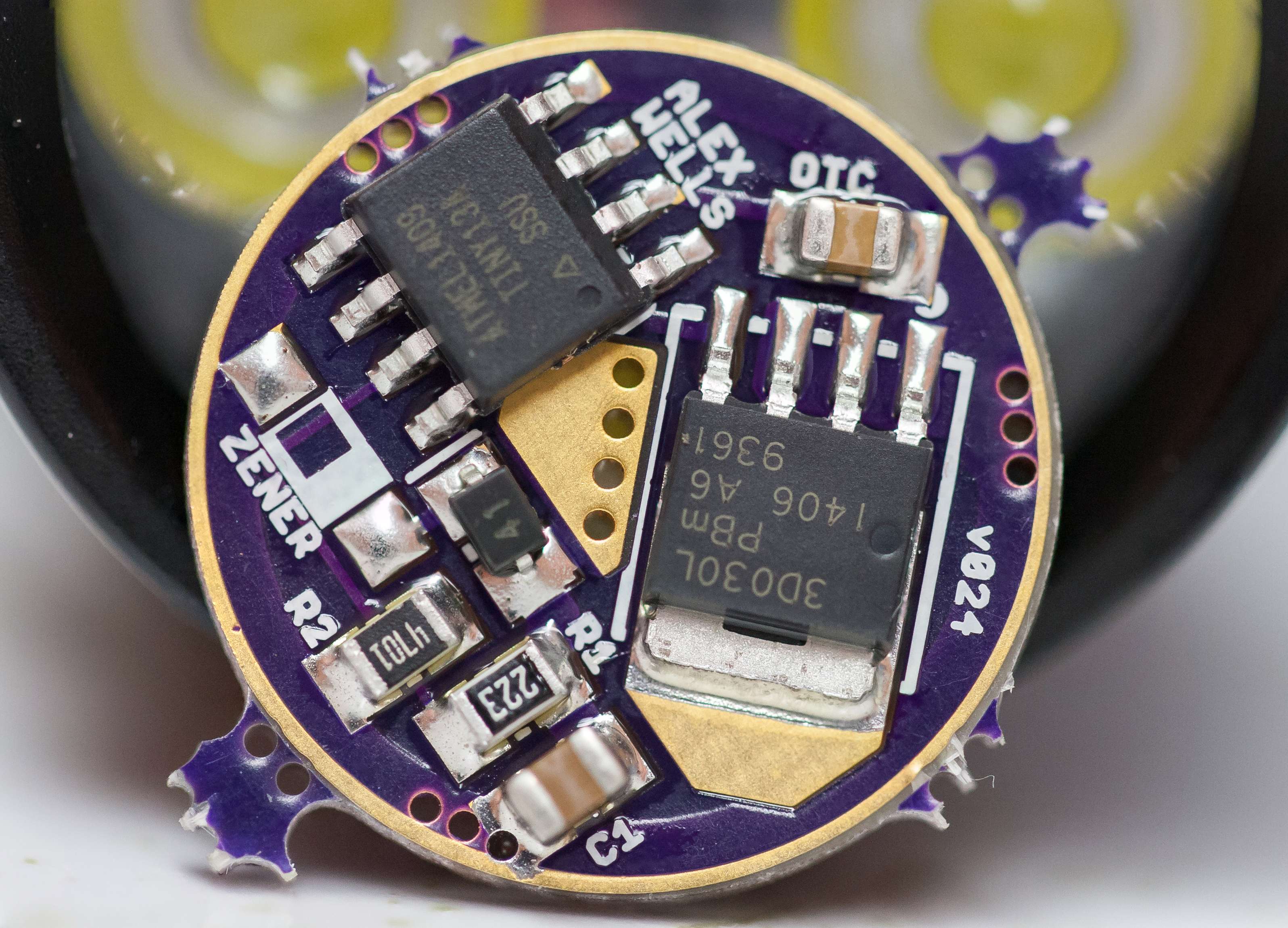
With the diode having the numbers 41 on it, and the 1 being where we would normally expect a line, does this line or 1 go to the point of the triangle?
The one in the picture is a SOD-723, which makes it harder to see since it’s so small. If I recall correctly it may not have been marked, I had to test it with my DMM to figure out the polarity. Either way you sure can’t tell from my picture.
Thank you sir. I LOVE using solder paste masks from OSHStencils! I MIGHT could have done it almost that neat, but this single sided board is just so easy with the stencil…
Looks fine to me. Resistors and diode are placed correctly, so is the MCU. Since the caps are unmarked we must assume that they are placed correctly. Is that glare, or is there some sort of (white) flux residue around the FET’s tab?
DoF appears to be very tiny in that shot! ~2.0mm I think?
So, in this normal configuration, can that Zener pad closest to the outer ground ring be used to solder a ground lead wire to, for establishing ground inside the pill with a screw instead of worry about press fit connection or outside soldering?
The Zener is OK for that. For my purposes I’ve been using the outer 3 legs of the FET - this makes for a larger and sturdier connection area for your GND wire.
That’s just solder around the FET, showing the white table it’s sitting on.
I only stacked 2 images, was taking a quick shot and did it by hand instead of setting up the tripod with the Macro rail on it.
All 3 outer legs are ground? Ok, that’ll work too. I was just thinking that big square pad sitting there with solder on it would be a good place for a ground wire. Keep it thin, with nothing under the wire as it were.
While we’re on the topic… another option might be the “1500 Watt 12 Interval Heat Gun” from HF, Item#69343. It’s (constant) ‘sale’ price is $29.99, couple that with the standard 25%-off-on-a-single-item coupon and you’ve got $22.49. Features seem similar to the Wagner tool, but who knows.