The line goes towards the point. There should also be a line between the pad and the MCU.
I looked up the datasheet on the diode and went with it. :)
The diode is marked with a 41. The "1" goes closest to the Zener pad and towards the MCU, the "4" is closest to the R1 pad and towards the 10uF cap.
Tried to look at your picture to see how you had oriented it on yours but the image wasn't clear enough to tell.
The one in the picture is a SOD-723, which makes it harder to see since it’s so small. If I recall correctly it may not have been marked, I had to test it with my DMM to figure out the polarity. Either way you sure can’t tell from my picture. ![]()
Please check this, you might be able to tell from this picture…
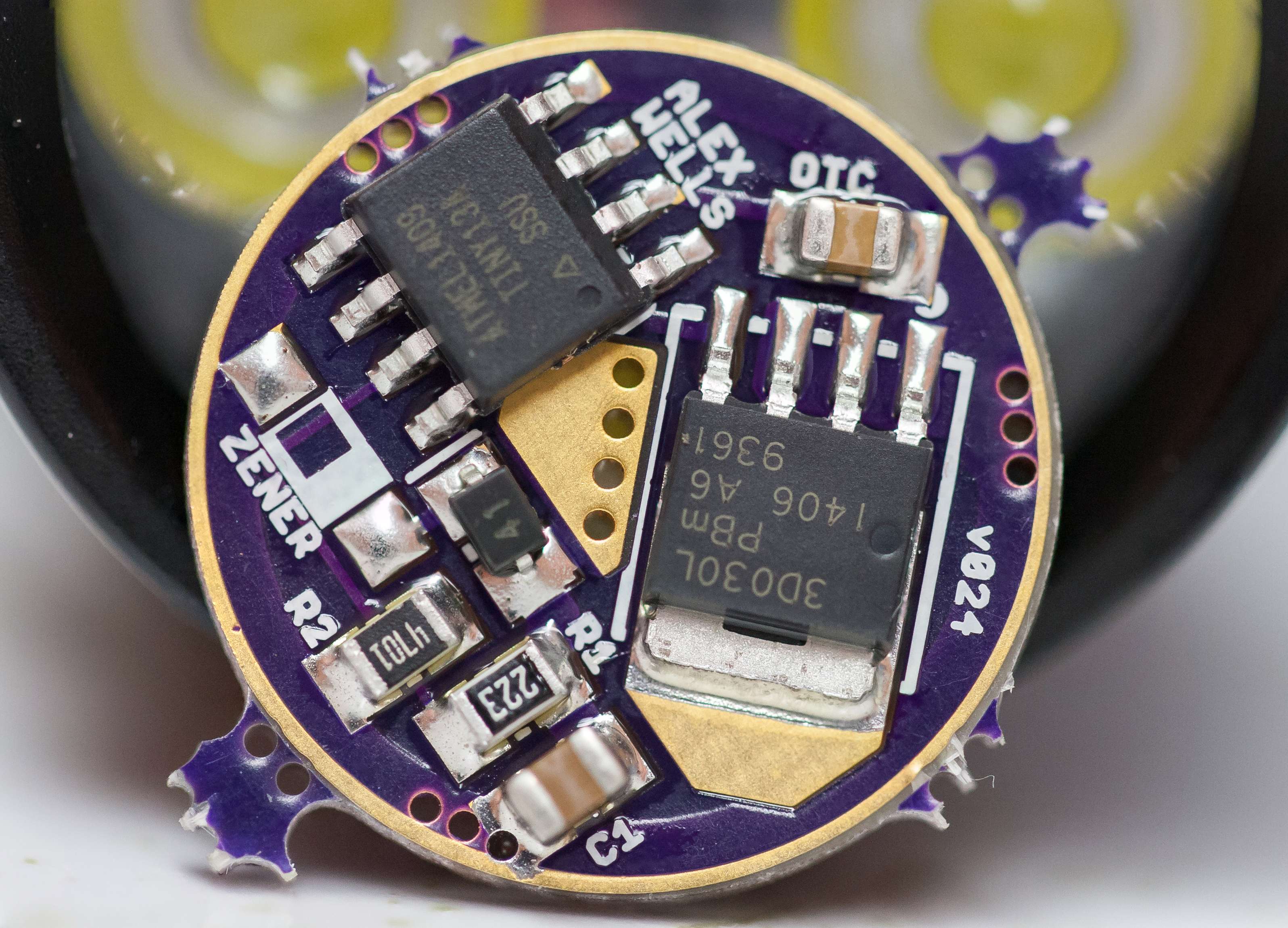
It can be clicked on for a larger view. ![]()
Caps crooked. ![]()
Edit - Dang nice work Dale.
Does that look nice Dale, i cant wait till i get my boards and parts and the best part my newer version of the 2008D
It was destiny, Kester EP256 style. ![]()
Thank you sir. I LOVE using solder paste masks from OSHStencils! ![]() I MIGHT could have done it almost that neat, but this single sided board is just so easy with the stencil…
I MIGHT could have done it almost that neat, but this single sided board is just so easy with the stencil…
Looks fine to me. Resistors and diode are placed correctly, so is the MCU. Since the caps are unmarked we must assume that they are placed correctly. Is that glare, or is there some sort of (white) flux residue around the FET’s tab?
DoF appears to be very tiny in that shot! ~2.0mm I think?
So, in this normal configuration, can that Zener pad closest to the outer ground ring be used to solder a ground lead wire to, for establishing ground inside the pill with a screw instead of worry about press fit connection or outside soldering?
That’s a stacked image. ![]()
The Zener is OK for that. For my purposes I’ve been using the outer 3 legs of the FET - this makes for a larger and sturdier connection area for your GND wire.
Crazy! I should expected as much. ![]()
That’s just solder around the FET, showing the white table it’s sitting on.
I only stacked 2 images, was taking a quick shot and did it by hand instead of setting up the tripod with the Macro rail on it.
All 3 outer legs are ground? Ok, that’ll work too. I was just thinking that big square pad sitting there with solder on it would be a good place for a ground wire. Keep it thin, with nothing under the wire as it were.
I definitely don’t see a problem with doing that.
While we’re on the topic… another option might be the “1500 Watt 12 Interval Heat Gun” from HF, Item#69343. It’s (constant) ‘sale’ price is $29.99, couple that with the standard 25%-off-on-a-single-item coupon and you’ve got $22.49. Features seem similar to the Wagner tool, but who knows.
Have you tested this with the Zener? Pull the standard diode and replace it with the 200ohm as usual, then do the math on the resistors for maintaining low voltage protection, right?
Realized I have an Olight M3X en-route, with an XM-L emitter and a 700 lumen rating. I also have an MT-G2 sitting around waiting for a home. 2 of em actually….
I have not tested this with a Zener. I have only tested 1s setups. You’re correct though, replace D1 with a 200ohm resistor and then do the LVP math and you should be golden.
Best place to solder a dedicated ground would be across the 3 ground pins of the FET since that’s where most if the juice flows.
wight, would be great to get your thoughts on two items.
First is regarding using your 26mm board to experiment with adding a thermistor circuit? These big multi-emitter lights need thermal protection more than pretty much every other light out three. ToyKeeper is building a program for garrybunk that should be able to use it to throttle power down when the thermistor gets too hot.

I thinking such a circuit should look just like a voltage divider you taught me about except for the following:
- R2 will be a thermistor instead of a resistor.
- There should be a capacitor parallel to thermistor. Probably can just be stacked on top of the thermistor if space is an issue.
It seems the power for the circuit should branch off the Vcc line. It would be good if the ground for the thermistor was directly linked to the ground ring for good thermal connection. I don't know what MCU pin pad to recommend. I would think any available one except PB3. I also don't know what thermistor or capacitor size to use.
Your 26mm board has some spare space. That and the fact that it will tend to be used in big high powered lights makes it seem like a great candidate. We will be get some insight with garrybunk's light, but that driver has a much different MCU Vcc circuit.
Secondly, what are your thoughts of paralleling a capacitor on R2 in a normal voltage divider circuit. I think it would smooth out the signal and might resolve the premature triggers that I think I may have been getting on my Crelant 7G10 build. I will be exploring this after I finish garrybunk's build.
EDIT: Clarified some wording.
ImA4Wheelr, you are correct that the circuit for using a thermistor should look like a voltage divider (because it is a voltage divider). I’m not certain which position will work best for us, I’ve seen diagrams with the thermistor in either position.
I don’t see what the point of the capacitor is (for either divider). I don’t expect for it to provide any smoothing.
Have you considered skipping the thermistor business and going with an all-in-one temp sensor? Microa has used LM45, RMM has been experimenting with MCP9700 (Post#625). MCP9700 sounds like a good one to me.
I did not include pads specifically for a temp sensing IC, but I did include pads. You may lay an MCP9700 across the pad attached to Pin3 and pickup GND right next to it. You’ll need an air wire to pickup Vcc but that’s it.
In response to your edit… the MCU Vcc circuit on both boards (when used for 2s+) is very similar AFAIK: it’s just a Zener and a limiting resistor.