Thanks again wight. Great info and thoughts as always. I think I understand what you're saying about buck having different issues regarding voltage dividing. I can see it will get real messy in here if we talk about your driver and buck. Sounds like we should discuss buck voltage dividing in garrybunk's mod thread (since that will be actively pursued soon).
I really like the idea of getting true thermal management in the DD environment and your 26mm driver seems like the best candidate for experimenting with it. When I get a chance do that, I will touch base with RMM so I don't reinvent the wheel.
More specifically, thinking about building a program… But I’m probably going to need actual hardware to test it on, or it’s very unlikely to work. Blind coding almost never goes well.
Regardless, I still doubt whether thermal protection is even relevant on a bike headlight. If the bike is moving, it’s unlikely to get hot enough to matter. I mean, unless it’s built really weird, like using a steel or plastic host… but IIRC this one is aluminum with heat fins and the intended use is to run it on medium or high (not maximum) during regular use. So, maybe 2.6 amps spread between two emitters. Doesn’t seem like it’s going to be an issue.
Would it be possible to fix a starting voltage with a Zener and use the thermistor to alter that in comparison to Vref? Then the cold voltage is constant for the entire battery cycle and goes down only with heat.
Update on my Quad. I used a PH-08 from FastTech to put a quad in, with a solid copper pill and BLF17DD Ver 3.0. But I was having some flickering issues. So I pulled the V3 and put the A17DD-S08 with ToyKeepers newest Ramping firmware, bits commented out that didn’t apply to this light. Still flickered. So I pulled the tail cap apart and Voila! Dirty aluminum retaining ring and cheap pcb with dirty copper trace!
So, I cut a circle of copper from a bit of copper sheet Scott sent to me (Thanks again Scott! ) and soldered a spring on it, bypassed the spring with a 22ga wire. Then filed down the aluminum retaining ring so it’s flat and new metal.
This A17DD-S08 driver allows the freshly charged Efest 35A to run 15.2A through the Quad XP-L V6 2C emitters! Folks, this is a pretty small light, making over 3000 OTF lumens! :bigsmile:
Um, the bad news is I only got about 7 seconds out of it on the lightbox at 4147 lumens, 3976 when it died, poof, just went out. So now I get to go back in and see just what happened. lol
I put one of those spongy white thermal pad things on the MOSFET (came off the driver in my Olight Javelot) and just ran it for 45 seconds in hand.
This bad boy gets HOT! But it seems to be working. It’s been pointed out to me that 15A off 4V is in the 60Watt range or somewhat like a good soldering iron.
The PTC is a physical safety feature, it is not what you refer to as “protection”. AFAIK all cylindrical Li-Ion cells have that (as well as a CID I think).
One way figure out whether it’s the PTC is to remote-mount the battery. I know that this flashlight does not make it easy, but it’s probably possible with a sliding clamp to hold the cell, a nice jumper cable clamp for the GND/Bat- connection, and some copper rod or whatever for the BAT+ connection.
Or you could just solder some big hookup wire directly to the light engine.
I’m assuming that if it is the PTC then the problem is the heat from the emitters, not the cell self-heating or anything.
The PTC is a thermal switch to help prevent overheating of the cell causing pressure build-up. From what I’ve been able to find online, if the PTC is triggered the cell will most likely be useless. This cell is working fine, recharging fine, working some more. So it really is doubtful that it’s the PTC causing issue here. (Positive Thermal Coefficient) This is the primary information I found. And just now, looking to double check what I was writing, I found this information that contradicts the previous articles (4 different sources)
“Problem
Most commercial, cylindrical lithium-ion cell design are
equipped with a positive thermal coefficient (PTC)
current limiting switch to provide hazard protection
against short circuits external to the cell. This device,
shown in Figure 1, is thin annulus consisting of a
specially irradiated polyethylene laminated with a metal
on both sides [1]. When exposed to an overcurrent
situation, this normally conductive polymer heats up and
changes phases to become several orders of magnitude
more resistive. Once the short is removed, the PTC cools
down and returns to its electrically conductive state. This
device has been a very effective method of providing
reliable short circuit protection in low voltage battery
assemblies. ”
This would explain why, after several seconds, the firmware caused a flash indicating power had been applied, even though I had not taken the light apart or opened it. The switch in the cell reset and power was again available.
So, is 15A+ the top end for the Efest 35A Purple cell? Leave it to me to have found that, huh?
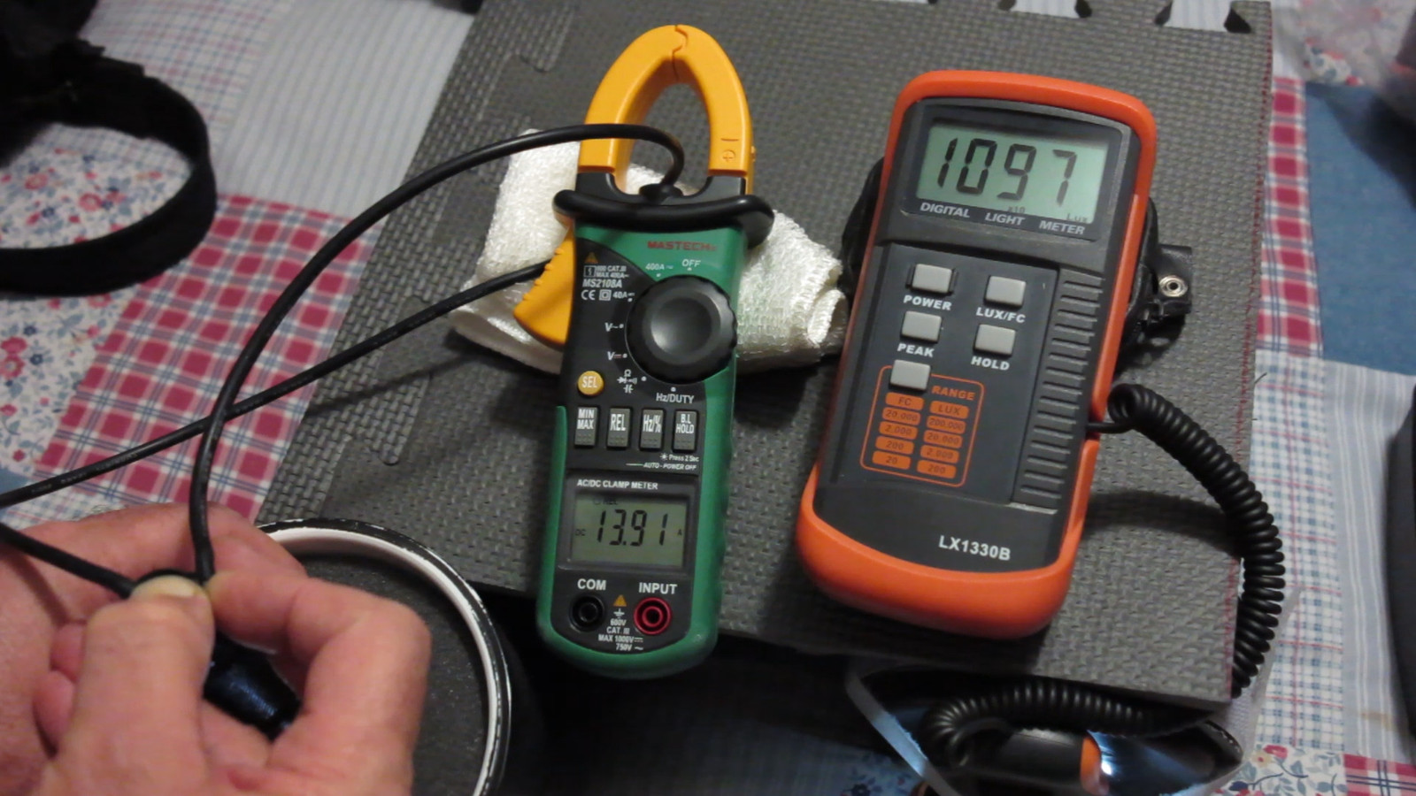
The Sony C5, fresh off the charger, didn’t quite allow 14A (13.61-13.91) and showed 3784 lumens at the highest, dropping down to 3450 by the time it was too hot for me to hold my thumb opposing the switch. (54 seconds, as per the video I took while doing this.) I should also point out that I was taking a tail amperage reading with a 14” long 12Ga wire through the clamp meter while the light was in the light box. So the lumens output was lower than if the light had been assembled.
This light with it’s chunk of copper under the quad only dropped 340 lumens in 54 seconds at extreme power levels, I’d say that’s not bad at all!
Point here being that your A17DD-S08 driver is a very capable little single sided slimline device!