Has anything been decided about the hardware, like which MCU will drive the indicators? Where is the voltage coming in, and is it getting divided to a standard range? In general, how is the hardware turning out?
I think the decision was:
- Remove the stock MCU entirely.
- Attempt voltage monitoring AND temp monitoring.
- Drive one or more of the stock indicators using the final remaining pin on the ATtiny. (EDIT: together, as unit. So just make them operate together and maybe turn on solid for low, then blink for critical… or something.)
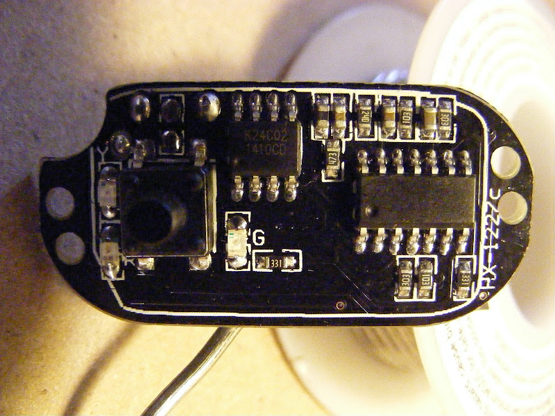
Hardware is the stock driver (pictures in Post 16) with the MCU pulled. Here is a schematic of everything but the 2 build-in buck drivers. I will adjust the voltage divider resistors initially and again after testing, if needed. I can also adjust the FW to fine tune LVP.

LED's 3, 4 & 5 are voltage indicator LED's. There are 2 buck drivers in the driver. Both will be provided the same PWM feed.
wight is correct. I sent you (TK) a PM earlier that I am willing to give up the temp. monitoring if that is holding things up or too difficult. And like wight said, getting voltage indicators to work in some fashion to provide low voltage indication (and I like wight's idea to just light / flash all 3 together).
-Garry
I think that’s actually ImA4Wheelr’s idea! Hopefully I recall that correctly.
I was under the impression that the code JonnyC had on Github for temp & voltage was functioning, but who knows. I could definitely be wrong about that, I have not tried it.
You are correct wight. That was my idea if we used a pin for temperature monitoring. Although 2 emitters at 2.6 amps does not sound like much, the light is very small and the bike may not always be moving. Also, Garry could decide to increase current in the future. So it seemed true thermal protection would be worth pursuing and that it should trump voltage indicator lights (but that is Garry's decision).
Hi all,
Have just discovered this forum and have been hooked on it for the past few evenings. I am an apprentice electronics engineer and find it all very fascinating. I have one of these lights and am planning on resistor modding then having a stab at an mcu. I’ve only ever used PIC mcu before and the attiny is completely new to me but when you come up with something that works I will most definitely be attempting to reproduce it. Thanks very much for all the work that you guys have shared thus far and please please see this project through to completion.
Regards Jacob
Welcome to BLF Jacob! We might be scrapping the idea of the custom driver and instead utilizing the newly available KD2 10 Step programmable driver. Well it will still be custom work as the KD driver is not a direct fit.
-Garry
Hi 180jacob. Sounds like you bring a very needed skill set to the hobby. Looking forward to seeing what you eventually set out to do. We only have a couple PIC programmers here. Some of the PIC's seem have some nice advantages over the Attiny's. It would be nice to see the hobby branch out that way. Right now, all the momentum seems to be with the Attiny13a. I don't know if we have any electronics engineers here on BLF.
This build be be completed. We're currently trying to figure out the best MCU/FW to use to give the light the most desired functionality. I really hope we develop a nice open-source FW/Hardware solution. One option, as Garry mentioned, would be to transplant the MCU (and I think eeprom chip) from the KD2 to the host driver. Garry will be evaluating the UI, mode separation, etc and then will make a decision if we will go that route. It does seem like a very attractive route as the KD2 driver can be had for about 8 bucks. If we go that way, I'm thinking of using the brainless KD2 driver to drive a couple off-road lights on one of my cars.
Garry has opted to utilize the MCU from the KD2 10 Step programmable driver. For any not aware, he requested KD make the driver available separately from the light. Last I checked it was $8.
After playing with the KD driver a bit, I have to say it is a pretty cool driver. Programmable levels, thermal and low voltage protection, and indicator lights basically cover all the features Garry wanted. I really like how it smoothly ramps to the next level.
I've spent a good amount of time trying to map out the circuits on the KD driver so that I can determine what needs to be done to transplant the MCU to to the HD-016. It's been frustratingly difficult due the black masking and traces running under components. I finally had to resort to sacrificing the KD driver by sanding off the masking.
This will be a pretty involved driver mod because it will require at a minimum that the MCU, EEPROM chip, and some resistors be transplanted. Another complexity is that the pin outs are completely different and almost every pin of the KD's MCU is used. There will be a lot of air wiring. There are some other circuit differences that may need to be addressed as well. I also hope to transfer the Red, Yellow, and Green indicator LED's as they have different meanings for programming and voltage indication. Not sure what the HD-016's green GITD cover will do to the colors.
Here is the driver with the toroidal inductor removed:

Driver with mask partially sanded off:


Here is a first draft of the KD circuit. It was written down as I studied the sanded driver and compared to pictures of the unstripped driver. It doesn't include some of the buck portion of the circuit as the HD-016 will provide that. I still need to verify the accuracy of the diagram. Once verified (hopefully tonight), I will compare the the HD-016 circuits and formulated a transplant plan.

Hopefully all goes smoothly. I will update the OP with a summary of all the mods once completed.
I’m glad to hear it’s moving along. I’ve been sick for about two weeks and barely managing to keep up with work, so I haven’t really stayed in the loop.
ImA4Wheelr, great job. I like that KD2 driver much and it's nice to see the drawing of it. Hopefuly you'll do it like this at DX forum (pic.source http://i.imgur.com/WzPgF8g.gif). It has identical user interface, but it's boost driver for 3 to 6 leds in series.

Maybe this drawing would help you somewhat.
Thank ledoman. That may be very helpful. Do you know if there is a free program out there that would enable me to create a diagram like that for the this KD driver?
Unfortunately not. I'm not EE, just end user of those driver.
Maybe Eagle can do that for me. I need to study this thread by Mattaus.
Your diagram will be good for verifying mine for the relevant parts of it. Thanks again ledoman. :)
Glad to see progress ImA! Sorry this project has become so difficult! I didn't intend to torture you when I asked you to take this on!
-Garry
No worries. Learning a lot. Hoping to wrap this baby up this or next week.
Eagle can do the diagram. IMO using a CAD program like Eagle is much less frustrating than attempting to map out an unknown circuit on paper.
I think jotting down observations on a piece of paper seems much easier than burning time searching for library elements for an unknown MCU and other components. Maybe for a more complex circuit, but for our drivers a sketch seems adequate.
Would be nice to document all tidy and all for future reference though.
One factor is how well you understand the circuit to start out with. The better mental image you have of the circuit, the easier it is to draw in either format.
There’s no reason to go running around looking for library components. Just pick something that uses the same package and go with that. It’s not like someone is going to flip a power switch on your Eagle schematic: it’s just a representation. More experienced Eagle folks may normally just make any missing parts, but I don’t usually bother for a schematic.