Just a side note… I’m thinking of changing the thresholds for battery check modes to more accurately reflect capacity instead of voltage. Currently it does one blink for every 0.3V above 3.0V. Most of the capacity is toward the top of the voltage range though, so this doesn’t map well to capacity.
Instead, I’m thinking of setting the thresholds to 3.0V, 3.5V (maybe 3.6), 3.8V, 4.0V, and 4.2V. Do you think these would get somewhere near 25% capacity for each blink?
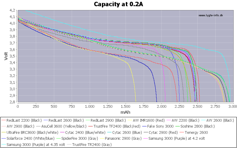
Edit: I’m basically talking about fitting it better to curves like hkj measured, but different batteries have rather different discharge curves so I’m looking for a happy medium:
ToyKeeper: that chart gets a little busy, maybe the signal to noise ratio is high. Let’s see, if we eliminate the lowest 3 lines (Yellow/Blue/Red - I think that’s an old IMR cell (AW IMR1600), an old Redilast 2200, and either an old Redilast 2600 or old Solarforce 2400???) that cleans it up a lot. Next if we eliminate the highest line, the uncommon-and-impossible-to-account-for-with-this-system (IMO) 4.35v cell, we clean it up further.
Now most lines stay together until around 3.70 or 3.75 volts. Around 3.7v seems to me to be the lowest voltage where we can assume that none of the graphed cells (other than the excluded 4) are on the wrong side of their discharge “knee”.
That said, discharge current may not be 0.2A, so there’s a lot to think about in that area. Basically we know that voltage depresses a lot under load, but here are two links to SilverFox and HKJ threads which are at least mildly related:
HKJ demonstrates approximately a 10minute recovery from (for example) 3.6v under 1A load to 3.7v under no-load. Recovery time seems to be similar for 3A, just with more voltage depression: about double I think. So in my example we’d be at 3.5v under load and it would take us 10min or so to rebound to 3.7v no-load.
Please also scroll down to the “Tables” section at the bottom of HKJ’s OP in that thread.
I guess what I’m getting at is that the user is going to have to have a ‘fair’ amount of knowledge to interpret the battery measurement output blinks. Also I’m probably saying that fairly high output resolution is necessary.
OTOH looking at HKJ’s data… if the output was just a binary >3.8v vs <3.8v indicator… that might be both useful and easy to understand? HKJ also makes some great observations in that post: “In the above curves, notice the difference in volts between the 10s and 1 hour trace, this is always below 0.1 volt, i.e. if measuring 10 seconds after load is removed, the error is not more than one 0.1 volt step wrong. Waiting two minutes makes the voltage close to the one hour value, especially at 3A load this wait will improve the precision.”
Thanks for the links. I thought I had seen those at some point but I couldn’t find them when I searched earlier today. It definitely answers my questions.
The measurements are being done at no load, so I initially used hkj’s lowest-amp discharge curve. His no-load data is better though. My readings get taken only a few seconds after the cell was last loaded, but it looks like the recovery curve is pretty steep.
If the curves were normalized so that they were all the same width, I’m basically looking for the average Y-axis values (voltage) which correspond to X-axis values (capacity) of 25, 50, and 75%.
The main difficulty I see is the high-amp cell curve vs the high-mAh cell discharge curve. High-amp has a well-defined “knee” around 3.55V while high-mAh cells seem to discharge more linearly (less-defined knee at 3.2V).
So, yes, the user will need to know what type of cell they’re using, in order to understand how low is “low”. At 3.7V (resting) a high-amp cell is almost empty, while a high-mAh cell still has about half of its power left.
In any case, the data we both found suggests that I should definitely raise the thresholds from 3.0/3.3/3.6/3.9/4.2 to something more like 3.3/3.6/3.8/4.0/4.2 if I want to accurately represent capacity (and the “recharge me please” value would be just one blink).
The thresholds under load are, of course, lower. I think I’ll stick with the 0.3V increments for that (for realtime indicator lights), since it means it will be green for most of its life and won’t go yellow/red until it’s genuinely low (or under very high load).
Sure thing. I think your thinking sounds pretty solid, but I’ll make one mild counterpoint. You indicated that the high capacity cells tend to lack that “knee”, but I think that’s actually just Panasonic’s cells: the NCR18650A, NCR18650B, and NCR18650BD. Most other cells of all types tend to have a knee I think.
Normalizing the graphs on the X-axis did not occur to me, that makes a lot more sense for comparison purposes.
Whoops, I'll fix that up. The Dual Switch is kind of the redheaded stepchild that doesn't get the attention that the other programs do. I actually haven't even used it yet other than in my test rig.
Funny thing is, I wrote this so that I could mod the S4 I bought a while back but never used. I still haven't modded it or used it :( It's an awesome light, but I'm so used to the overhand grip and being able to switch modes with just my thumb that a C8 is my go-to light.
Every time you turned off the light it would just default back to off, unless you set the lowest mode to something other than off then I'm pretty sure it would default back to that mode.
I haven’t seen this mentioned anywhere so I guess it’s a no brainer to connect the switch to ground? But do I wire star 4>switch>GND for the Dual Switch version?
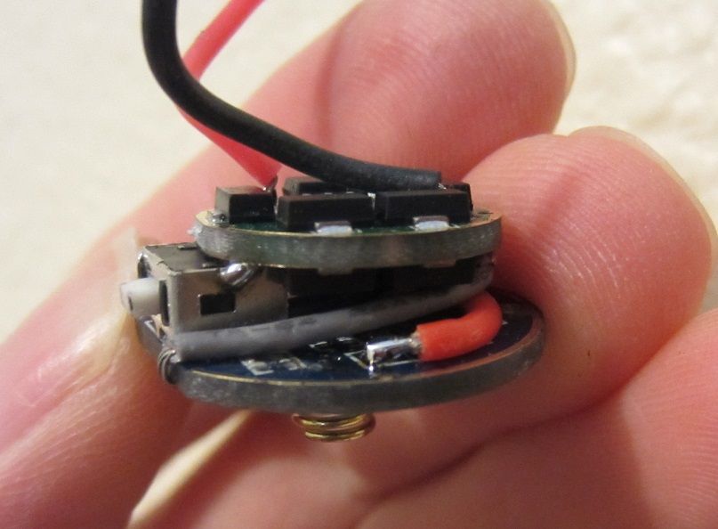
Everything worked well and looks fairly trim and proper. I don’t think it warrants its own thread, but what I did was remove all of the components from the stock driver contact board and then made the necessary connections for the switch and power. One leg of the switch is jumped to ground, the other leg is connected to a wire which wraps around the flat side of the board and makes its way up to star 4. I didn’t have any really tiny wire (or bother to use a single strand of copper) so Kapton tape was necessary to prevent the switch wire from shorting on the driver retaining ring after the driver was installed. The mode spacing I went with was 12,70,255. It isn’t night time yet but the spacing seems pretty good. I gas de-domed an XM-L2 U3 on a 16mm noctigon (didn’t have any 20mm ones) and bolted it up. The holes that the stock LED board mounting screws “thread into” are actually not threaded at all, but they are the perfect size for a 4-40 cut tap so I tapped them and used some 4-40 BHCS. 3/16” is a good length.
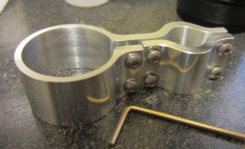
Now I just have to make the rifle mount. I’ll update this post when I’m done with it in a few hours.
————————————————- Edit: There we go. Now off to the folks to see if it fits….
Edit: nope, I underestimated the size of the barrel. I’ll remake it with a hinge and a pull pinscrew so the light can be removed instantly. My parents have too few lights to let it sit on the rifle unused so it should be removeable easily. Good point about the physical connection of the driver in this application wight; I hadn’t considered it much. Fortunately it is only a .22 and has virtually no recoil so I think the solder joint on either side of the switch housing will suffice in this instance.
No problem. Your work looks good. One thing to consider, especially for a rifle light IMO, is the physical connection between the two PCBs. It looks like your only rigid physical connection is the switch casing being soldered onto the GND ring of the driver. If that’s the case consider adding epoxy or something to stiffen up the bond. In fact, consider air-wiring that connection and then using epoxy/whatever to do the physical connection. Just my two cents!