Hey guys, i have downloaded johnnyc latest code from his signature and now it works accordingly. Thank you so much :bigsmile:
Awesome, thanks for making us aware of the issue!
I am trying out the Dual Switch version of the software and I get an error during the compile to hex:
“variable ‘modes’ must be const in order to be put into read-only section by means of ‘attribute((progmem))’
line 115 column 18
Anyone know the issue?
IIRC syntax changed between versions of AVR Studio. What version do you have?
6.2 build 1502.
The actual line of code related to the error is: PROGMEM uint8_t modes = { MODES };
I also edited the line at the beginning of the program to change mode spacing: #define MODES 12,70,255
Right, the fix is in post #413 I think. STAR Firmware by JonnyC - Source Code and Explanation
Subsequent posts indicated that this fix worked.
Whoops, I'll fix that up. The Dual Switch is kind of the redheaded stepchild that doesn't get the attention that the other programs do. I actually haven't even used it yet other than in my test rig.
I just pushed the changes to Git.
Thanks a lot wight and JonnyC.
I am putting this driver in a Convoy L4. I sure am glad to use this firmware!
Funny thing is, I wrote this so that I could mod the S4 I bought a while back but never used. I still haven't modded it or used it :( It's an awesome light, but I'm so used to the overhand grip and being able to switch modes with just my thumb that a C8 is my go-to light.
Oops, I meant L4, not S4. :party: How would the momentary version of the firmware behave in the L4 I wonder?
Ha! I meant L4 too :)
Every time you turned off the light it would just default back to off, unless you set the lowest mode to something other than off then I'm pretty sure it would default back to that mode.
I haven’t seen this mentioned anywhere so I guess it’s a no brainer to connect the switch to ground? But do I wire star 4>switch>GND for the Dual Switch version?
Yes.
Dang wight. You fast. :bigsmile: Thanks again.
Edit: Anyone in the mood for a sandwich? ![]()
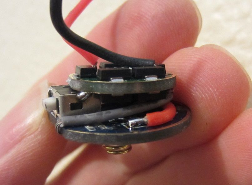
Everything worked well and looks fairly trim and proper. I don’t think it warrants its own thread, but what I did was remove all of the components from the stock driver contact board and then made the necessary connections for the switch and power. One leg of the switch is jumped to ground, the other leg is connected to a wire which wraps around the flat side of the board and makes its way up to star 4. I didn’t have any really tiny wire (or bother to use a single strand of copper) so Kapton tape was necessary to prevent the switch wire from shorting on the driver retaining ring after the driver was installed. The mode spacing I went with was 12,70,255. It isn’t night time yet but the spacing seems pretty good. I gas de-domed an XM-L2 U3 on a 16mm noctigon (didn’t have any 20mm ones) and bolted it up. The holes that the stock LED board mounting screws “thread into” are actually not threaded at all, but they are the perfect size for a 4-40 cut tap so I tapped them and used some 4-40 BHCS. 3/16” is a good length.
Now I just have to make the rifle mount. I’ll update this post when I’m done with it in a few hours.
————————————————-
Edit: There we go. Now off to the folks to see if it fits….
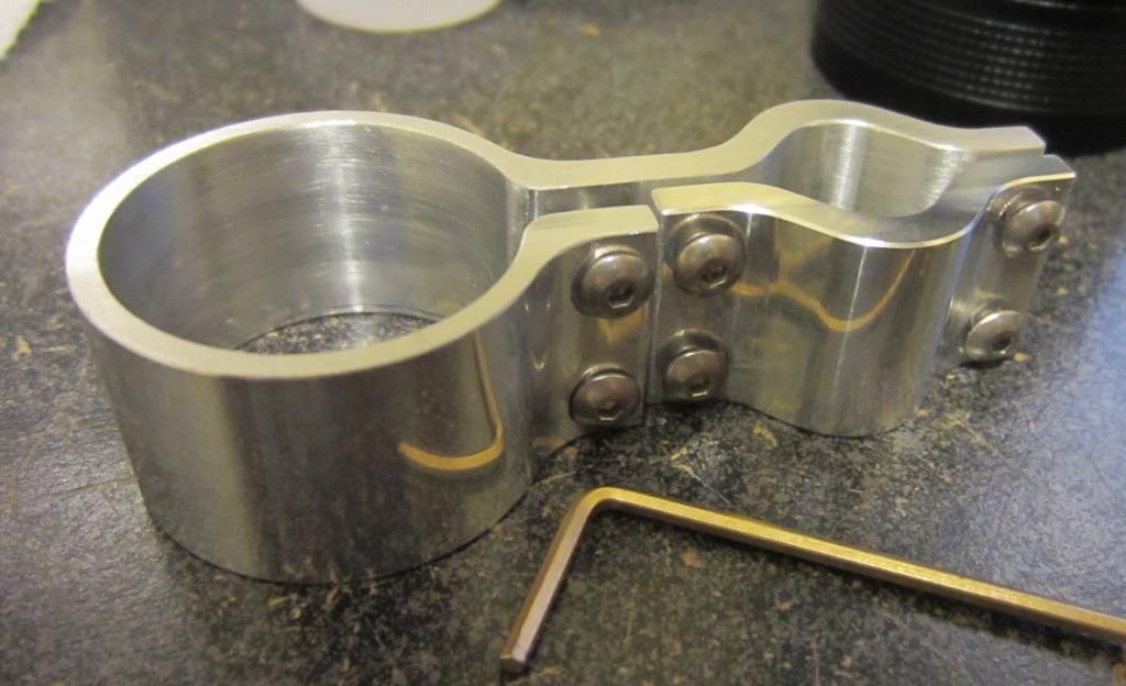
Edit: nope, I underestimated the size of the barrel. I’ll remake it with a hinge and a pull pin screw so the light can be removed instantly. My parents have too few lights to let it sit on the rifle unused so it should be removeable easily. Good point about the physical connection of the driver in this application wight; I hadn’t considered it much. Fortunately it is only a .22 and has virtually no recoil so I think the solder joint on either side of the switch housing will suffice in this instance.
No problem. Your work looks good. One thing to consider, especially for a rifle light IMO, is the physical connection between the two PCBs. It looks like your only rigid physical connection is the switch casing being soldered onto the GND ring of the driver. If that’s the case consider adding epoxy or something to stiffen up the bond. In fact, consider air-wiring that connection and then using epoxy/whatever to do the physical connection. Just my two cents!
Woah! Snazzy looking. :heart_eyes:
I realized that I’d spoken out of turn as soon as I saw your snazzy barrel-clamping mount made up for such a small barrel. I agree with you.
How did you make that clamp? That's really nice. Are you hiding some nice machines and machining skills from us? ;)
Looking back at your posts:
1.) Very nice firmware flashing guide!!
2.) Did you ever develop those Mag heatsinks?
Thanks fellas. :bigsmile:
Yea, I’m a professional machinist and happen to have a Haas vertical machining center in my garage. I really need a turning center though. In due time…
I did develop the mag heatsinks but I’m still working on the battery carriers. It’s going to be a whole kit.
Ive recently thought about offering machining services to BLF. I saw Nitro’s x6 heatsinks thread and thought… I could beat the price he was quoted by a few dollars per part. I’m more focused on starting a full fledged flashlight manufacturing company at the moment though.
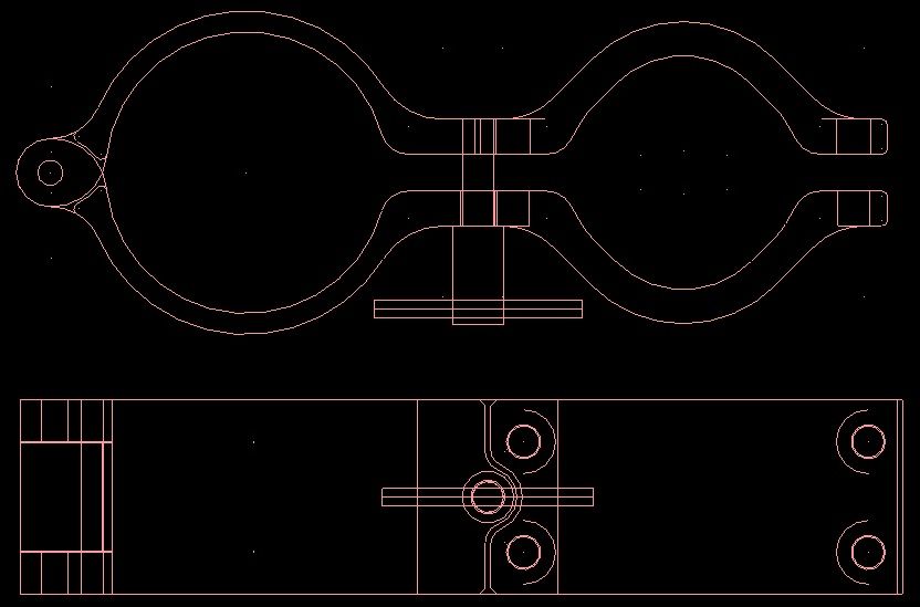
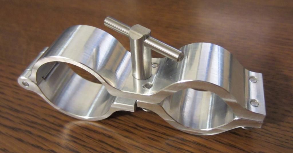
There we go. This new clamp design is almost sufficiently complicated, just how I like it. (when you see my mag heatsink you will get the joke)
On second thought… I think I will make a post about this L4 build when it’s done. Enough derailing this thread!
Edit: From concept to reality. It better fit this time cuss that took like 13 hours…. (I used my “micrometer eyeballs” on the barrel because I didn’t bring a measuring tool) I made the “T screw” handle bigger so it would be easier to use. More shots to come in the post I’m making about the build.