Probably yes. The last batch I ordered about three months ago was still equipped with ATtiny13s.
Yes. Well, not truly constant 50/500mA, but a PWM level that averages out to this values.
No. This would require one write cycle to the EEPROM for every light level passed during the ramping. Since the EEPROM ist rated for "only" 100,000 write cycles, this would probably wear it out in less than 1000 ramping operations.
Yes. Put it in the extended mode group, but not the main one.
It would be nice if someone makes a frontend for all that load of apps with dropboxes to quick select custom driver options and autocompile the choices in a flash ready format.
It can be done but someone must really sweat that one app. Willing to donate a few bucks for the martyr who would like to try such project and i bet i'm not the only one willing to contribute.
I really do not like the idea of learning some C++ or what is this based on (at least is not plain assembler).
Not me. I've even given up on keeping all possible driver configurations within a single source file. It's much easier and less error prone to just paste together a new driver from a library of standard functions and then add some glue code to make it all work together. At least if you know some basic C programming.
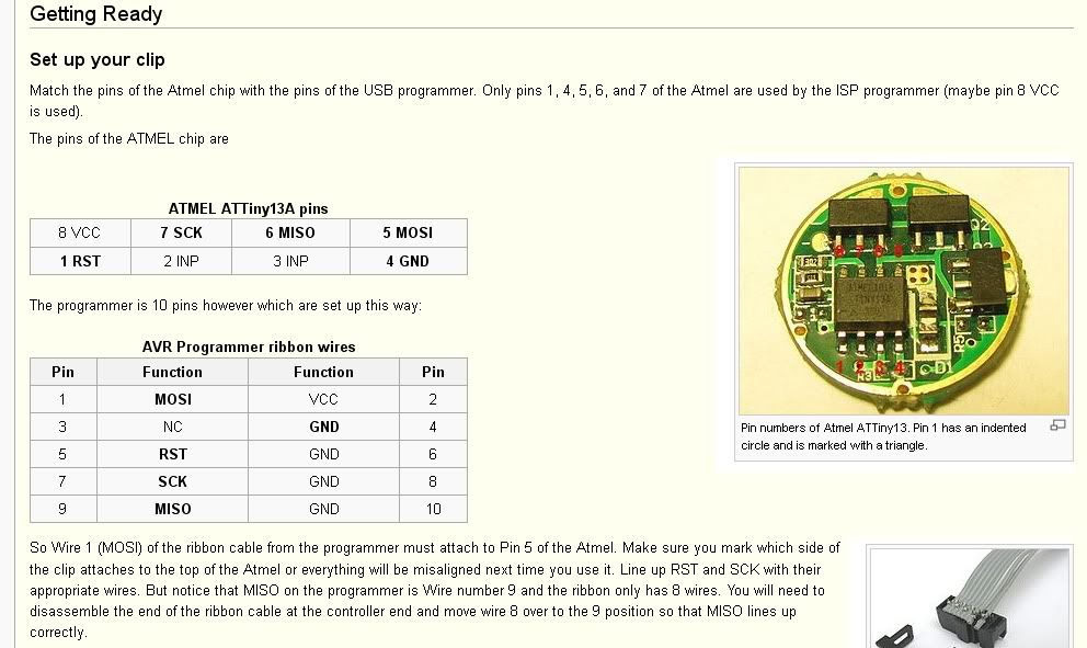
Actually the only reason i don't have the hardware yet is i never fully understood the rewiring of the soic clip to the usb programmer interface as from what i gathered have to be fiddled with.
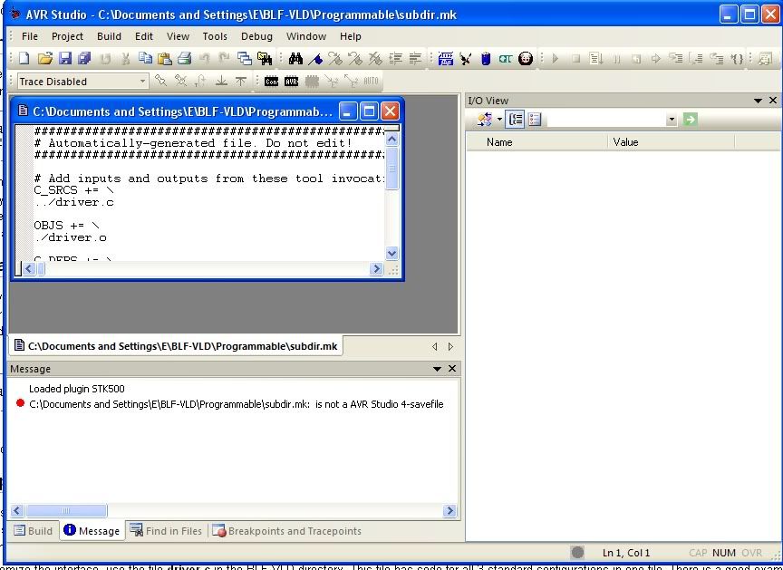
I have been following this thread with great interest (thank you Tido and everyone for the resource) and have purchased an avrispmkII and 3M soic clip. I am trying to reprogram a 2.8amp (8x 7135) driver that I purchased from Shiningbeam. I've hit a snag. Below is a screenshot of the error message I'm receiving. At first I thought the connection was bad but the green light comes on after I run the command, apparently indicating that the chip/target is receiving power. I've checked pinout three times, and I seem to have continuity in all pins. Any ideas from anyone? Is this the type of message I would get if the reprogramming fuse is set to prevent re-writing? Anything else I could check?
-Jon
Macintosh-3:~ JCI$ avrdude -P usb -p t13 -c avrispmkII -n
avrdude: stk500v2_command(): command failed
avrdude: stk500v2_command(): unknown status 0xc9
avrdude: stk500v2_program_enable(): cannot get connection status
avrdude: initialization failed, rc=-1
Double check connections and try again, or use -F to override
Looks like your connection isn't good, but I gave up a while ago I hit a dead end with my programming at this point. I actually de soldered a tiny13 chip to play around with so I can get the connections on easier. Sorry I couldn't be more help.
Use your multimeter and go from the clip to the programmer and make sure there is continuity again. It is written kind of weird I had to do mine twice because i read it wrong the first time before i got the right connections.
Thanks for the suggestion, I double checked the continuity with DMM and even soldered the leads directly to the pins on the chip, and the continuity was good between avrisp board pins and the chip pins. I don't know what else to do. I have another question: if you test the voltage between the vcc and gnd pins on the programmer (avrispmkII), should there be a constant voltage of 5V? Mine is showing basically no voltage between vcc and gnd on the programmer. I know I'm using a power usb.
So I just finished reading a review of the avrisp mkII, and it happened to mention that this programmer only senses voltage, but does NOT supply power to the target. Oops. So, I connected an xml to the driver, and soldered up a simple switched circuit to power the driver with 1 18650 3.7V li-ion, and wouldn't you know it, now I get a response! Of course, being me, I don't get the correct response:
When I first saw this thread, I was excited. I was thinking that I could get a 4-Mode driver w/memory, High-100%, Medium-50%, Low-15%, Moon-light-2%.
This conversation has gone so far over my head, that I'm back to searching the internet for an alternative. I don't think that this level of modding is EVER going to be within my reach 8-( .
Just to throw in my 2¢, if anyone gets to where they are custom programming some of these drivers, I'd like to buy 3-5 of them. Nothing fancy, just 4 modes, no strobes, w/memory.
Let us non-programmer types know. I'm still going to keep watching, but I'm not understanding a lot of what I'm reading.
Let's make a pool to make someone savvy make a few custom flash ready images with desired modes for us to use. That's it.
Get the soic clip the usb programmer load that load of apps and flash rightaway. About 5 versions per drivery type (the most common would probably fit 90% of requests). Unless i'm missing something it would certainly be doable.
4 modes with low low, 3 modes with XY spacing, 4 mode H-M-L or L-M-H with beacon. etc...
So, I finally am able to flash Tido's code to my drivers! The solution for me was to buy a USBtiny programmer kit from Adafruit, which requires assembly but which also powers the target board. Once I connected my attiny13-controlled SB 2.8A driver to this programmer, I had no problem. Next up is tackling the code so that I understand it well enough to set custom levels for a 4-level fixed mode no-memory driver. I think I am starting to understand, although I agree with the others that having the simple, programmable, and fixedmodes code in separate files in C would greatly increase my understanding. If I ever get the fixedmodes code sorted by itself I will post it (with Tido's permission).
I also have a question about pinswitch: does this feature allow you to program to fixed groups of modes (two sets of Low-med-high for example), where the mode sets can be selected by the state of the pinswitch pin? If so I am interested in learning how I might include another switch, such as tightening/loosening the bezel or tailcap, to change the pinswitch state and access the alternate mode set. Does the attiny13 have the memory for something like this, or am I misunderstanding the pinswitch feature?
I've successfully reprogrammed several drivers now, using a USBtinyISP programmer that supplies voltage to the target through USB power. I'm now working on modifying the code to so that I can have 4 fixed modes, similar to the changes sixty545 outlined for another member.
My problem is similar to others who have tried to build the code in AVRStudio: the error message "undefined reference to 'start_wdt' " comes up continually. I've solved the util.delay issue by defining the speed of the CPU, however I don't know where to start with this last error. I'm positive I have not changed anything in the code that would cause this, as I tried building the code without any modifications and this error still appears. It also occurs with an older version (0.3) of the code I downloaded. Does anyone know why 'start_wdt' is not defined in this code, and how I can fix this so it will build in AVRStudio5?