lol - don’t hold your breath.
Don’t give up mate! PM Vinh on the other forum, he has rooms of spare parts! Perhaps slight exaggeration!
Alright, hope everyone had a good break over the holidays!
Still no beamshots I’m afraid, we have half a meter of snow outside so those will have to wait a bit.
-
I’ve got some new super exciting runtime graphs though! Yay! ![]()
![]()
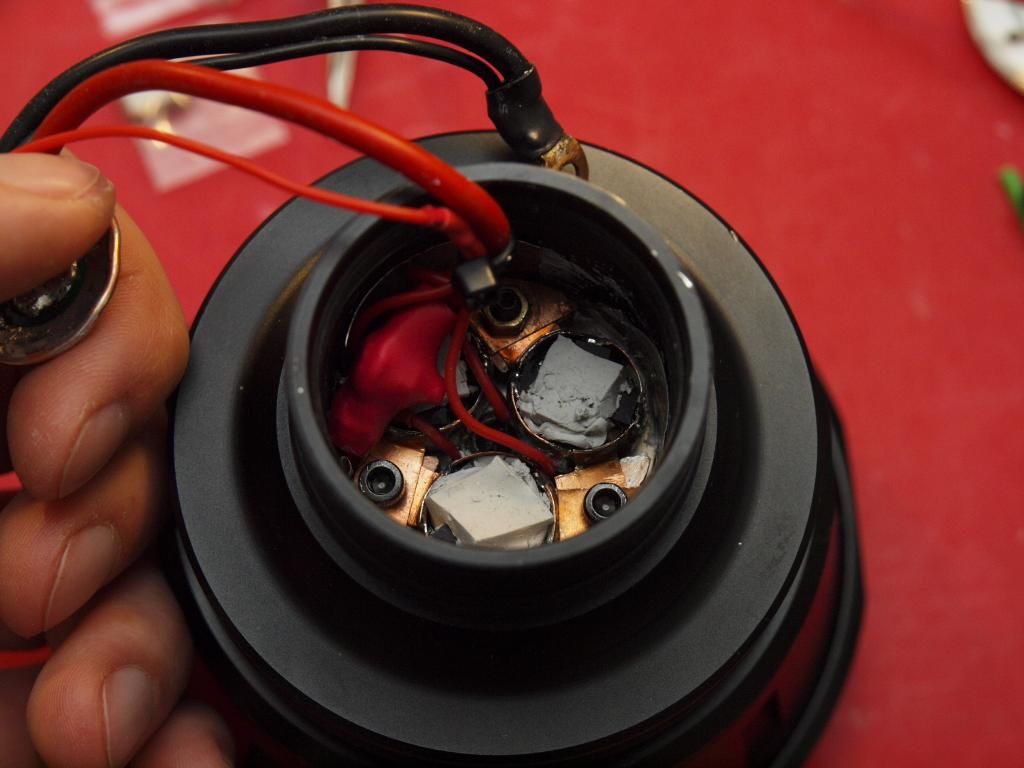
I had a go at maximizing the heatsink stuff inside the driver cavity and then ran the same setup as the last test to see if I could see any difference in the output behaviour.
All I really did was wedge some bits of thin aluminium sheet in between the driver assembly and the cavity wall, press some TEM cubes into the middle of the 7135 slaves (just to try and homogonize the temperature within all those 7135s) and apply a bit of thermal paste where needed.
I also touched up a solder joint on one chip that looked suspect and could potentially have caused a flicker on one particular emitter. That was something slightly annoying I noticed each time the light was warming up. I probably didn’t solder one 7135 ground tab perfectly with the copper sink rings causing it to heat up faster than all the others.
Not sure yet if that has been fixed but I definitely hope so.
It’s a mess in there and I wasn’t too hopeful that it would actually do all that much but the test results are pretty significant!
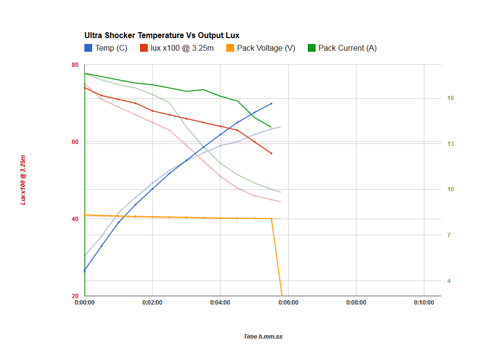
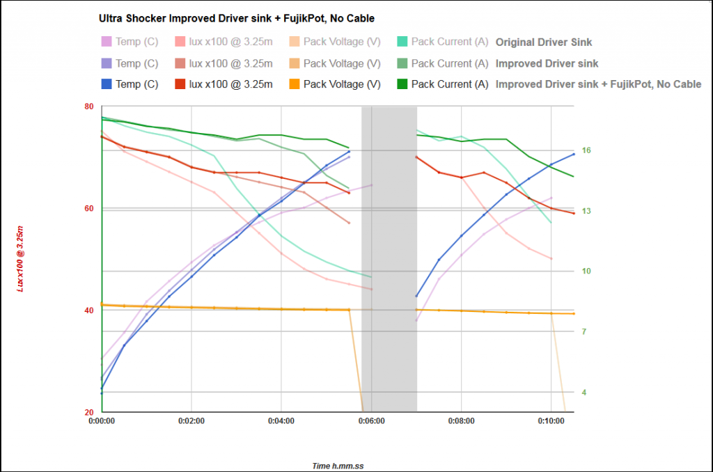
( Faded graph is old comparison test done before the heatsink improvements, solid is the new test. )
Everything was set up the exact same way as the first test except that the starting temperature of the light was around 4 degrees C cooler.
So I’m very pleased with these improvements. It’s really obvious that the light is now able to maintain considerably higher output for longer, the steeper part of the output curve now starts at 4.5mins rather than at 2. Temperature on the outside of the light also gets considerably higher and continues on towards 70 degrees, at around the 5.5 minute mark I saw a larger flicker in the output and decided to call it a day at that point! Haha, made me jump a bit tbh! ![]()
I suspect that was caused by one entire driver puck getting too hot and calling it quits, didn’t investigate which one because I wasn’t too happy running the light at that kind of temperature.
Next I’ll do a test with the battery pack cable again and see what real world performance looks like now.
Seeing how much better things are running now, I may well go back in and pot the entire driver assembly.
Cheers
Linus
You gotta love that temp line. 
Haha there’s no stopping that bugger! If I keep tweaking I might just get it vertical! ![]()
But to be fair I’m loving the waft of nicely heated air rising up to my hand on the comfy cool handle! Only need to bring one glove out in the snow. 8)
Edit: Dammit, the flicker is still there. Number 1. driver/emitter (top center) is the culprit, my re soldering didn’t do the trick. Really hope I don’t have to take everything apart again…urgh…
I’m really starting to hate these 7135s! ![]()
Test done with fully assembled light, (no current measurements for sake of seeing real world output performance)
…too tired to really figure out what’s going on but I’m a bit surprised. Is driver heat STILL the dominating factor dropping performance or does pack voltage now come more into play?
You can see the two output lines are perfectly parallel for a small section of the test, the cable setup a bit lower output (are we seeing the 0.6v cable losses?) but not much resembling a regulation phase before that. Just a bigger collapse in output over the first 1.5minutes.
Aha! Think I’m onto something here, environmental cooling system! Bet you wish you had this type of thing down in Aus ey MRsDNF? ![]()
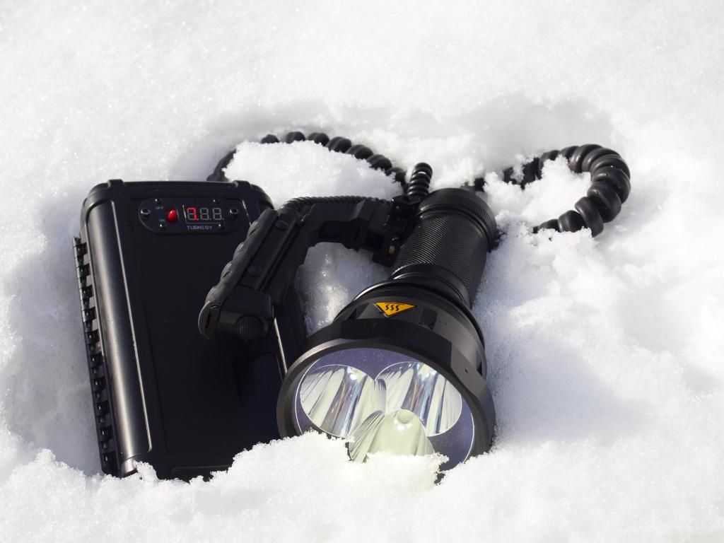
Not the most portable system but very effective! 8)
The driver issues have driven him insane! J)
Certainly seems that way, I must have truly gone insane to drown my entire driver assembly in fujik!
…what have I done…. seriously hope it helps! ![]()
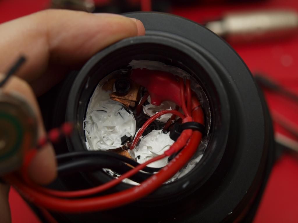
It looks like the worst kind of chinese assembly line practices in there! ![]()
I just got back up to speed on this (I was ~79 posts behind…). Lots of impressive work. The new driver stacks look great, big improvement. >16W through those 7135’s sure is tearing stuff up. Your graphs are great and informative.
Don’t forget the risk of an accidental hot dedome.
It’s best to solder an extra pair of wires onto the emitter MCPCB and bring them off to a test point on the side. I’m not saying I always do this (I do not always do this.) but it’s much safer for both the operator and the $20 LED.
Don’t hate me<ducks>, but I’d better suggest the standard troubleshooting step: swap emitters between two driver sections. Flickering at high currents could be caused by damaged bonds in the emitter itself.
Hmm, good point I hadn’t thought of that.
I have some heavy welding glass, maybe I can watch the emitter closely while it happens to make sure there aren’t specific sections of the array going offline. It certainly seemed like behavior I’ve come to expect from a single 7135 chip going toasty but I’ll investigate.
It’s not a tragic problem, not really noticeable during normal operation but still a little annoying if I can’t get rid of it. The emitter isn’t losing a lot of output, it’s really just a small drop in brightness that starts with a twitch or flicker and then seems to stay at the lower level from then on. My power meter isn’t quite granular enough in it’s current reading to show exactly by how much the current drops during the flicker but gut feeling is I’m losing about 0.380ma of brightness… ![]()
Similar stuff happens later at a much greater extent when the other drivers reach critical temperatures.
-
First I’m hopeful that my fujik drench did something to help the situation, if not I’ll have to see further. Frankly I’d be much happier to find a dodgy emitter at this stage than the thought of having to dig out and disassemble the whole driver assembly! |( :_(
Now that you mention welding glass that stirs my memory. IIRC another BLF member had a failing MT-G2 they viewed under welding glass. Probably DBCstm. Ah yes, here we are:
Damn that’s crazy, I didn’t know they did that. Never had an emitter fail on me before so I didn’t even consider it.
I’m really curious now to take a look at the emitter at full power to see what’s going on there.
I did have to reflow one of these emitters back when I got them, but checking back on photos there’s no correlation to the troublesome emitter.
I wonder if this might also explain some of the strange current draws I’m seeing, never quite getting up to where I expect them to be even with what I consider plenty of voltage overhead. Maybe the 7135s aren’t completely to blame after all, we’ll see if they can redeem themselves. ![]()
Cheers for the heads up!
Linus
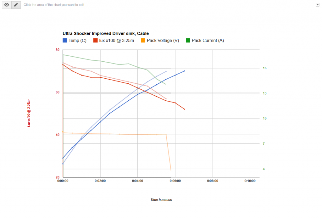
Ok, here are the final results after the fujik potting.
The graph is a bit of a mess because I overlaid the first two no-cable tests to show the direct differences that upgrading the driver heatsinking has made.
I’m glad to see that potting in fujik has shown another improvement, more subtle this time but still a worthwhile improvement resulting in a flatter overall current/output plot. Particularly obvious after the 3.5 minute mark where current seems better regulated (why it jumps up suddenly I have no idea, but I’ll take it!) and output is considerably higher than before as a result. The output heat cliff is pushed further back and is now very close to my 70degree temperature cutoff on the heat sink. When I called it a day at 5.5minutes I was still seeing 16.31 Amps draw. Nice!
Output heat sag at the emitters is obviously also a factor in all this, but even without considering the drop in current from the start of the test I’m only seeing about a 15% drop in lux over the course of the test. That’s pretty acceptable to me considering the exceptionally high power levels we’re talking about here.
I also tried to repeat the cool off and retest method of the very first test to see how things compare. I failed to get the light back to the same temperature but pack voltage and output was very similar. Actually they track amazingly well just after the turn on and even with a higher overall starting temperature it’s obvious that performance is maintained far better than before.
-
Overall I’m pretty pleased with the output characteristic of the light now. I still need to see how things have changed in the fully assembled light but this gives me confidence that the driver heatsinking related performance is now about as good as I can get it. Anything I can do to improve resistance losses from here will likely result mostly in higher output.
-
Unfortunately the bloody flicker is still present, it seems to start right around the 2.5 minute mark and looking closely at the offending emitter through the welding glass I see nothing at all dodgy with it. All array tiles are fully lit, very even and frankly I can’t directly see any flicker at all while looking at the emitter this way. It’s only really obvious when shining at a white wall and covering the other two reflector wells with my hand, it’s the kind of thing you catch in your peripheral vision more than when directly looking at the hotspot.
Well I was hoping it was the emitter that was obviously at fault, it might still be but if so only in a subtle way, maybe it will get worse and become more clear as the light is run in?
I think it’s most likely that I damaged a 7135 chip in the stacking process, either through bending the legs (not recommend I know but had to be done) or through applying too much heat. It may even heat up, flicker, go offline completely and then flicker back online as the overall temperature gets higher. Possibly a stretch but it might just explain the jump in drive current I see around the 3.5minute mark… ![]()
I dunno it’s too complicated with all these chips, trying to keep track of all the variables is doing my head in. The 7135s are probably all going through varying degrees of not working 100% right at these temperatures and all I’m seeing is the sum total if their combined agony! ![]()
I don’t really want to desolder the emitter wiring to swap over and test since that part of the light, i.e the ground flat insulated solder blobs and the alignment of the emitters is quite a pain to get right. I think I’ll live with the problem for now.
-
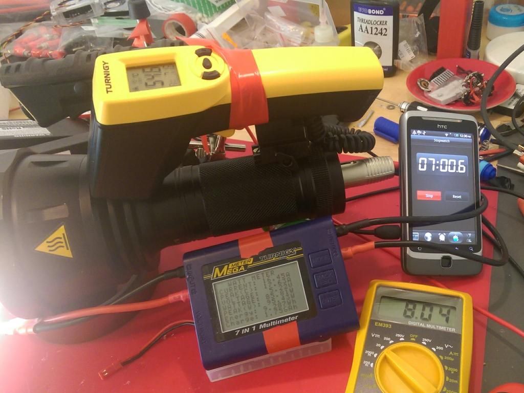
Edit: And here is the test setup. Got this going pretty well at this stage, I can just snap a photo with my other phone every 30secs and get all the data bar the lux reading in one easy snapshot. :bigsmile:
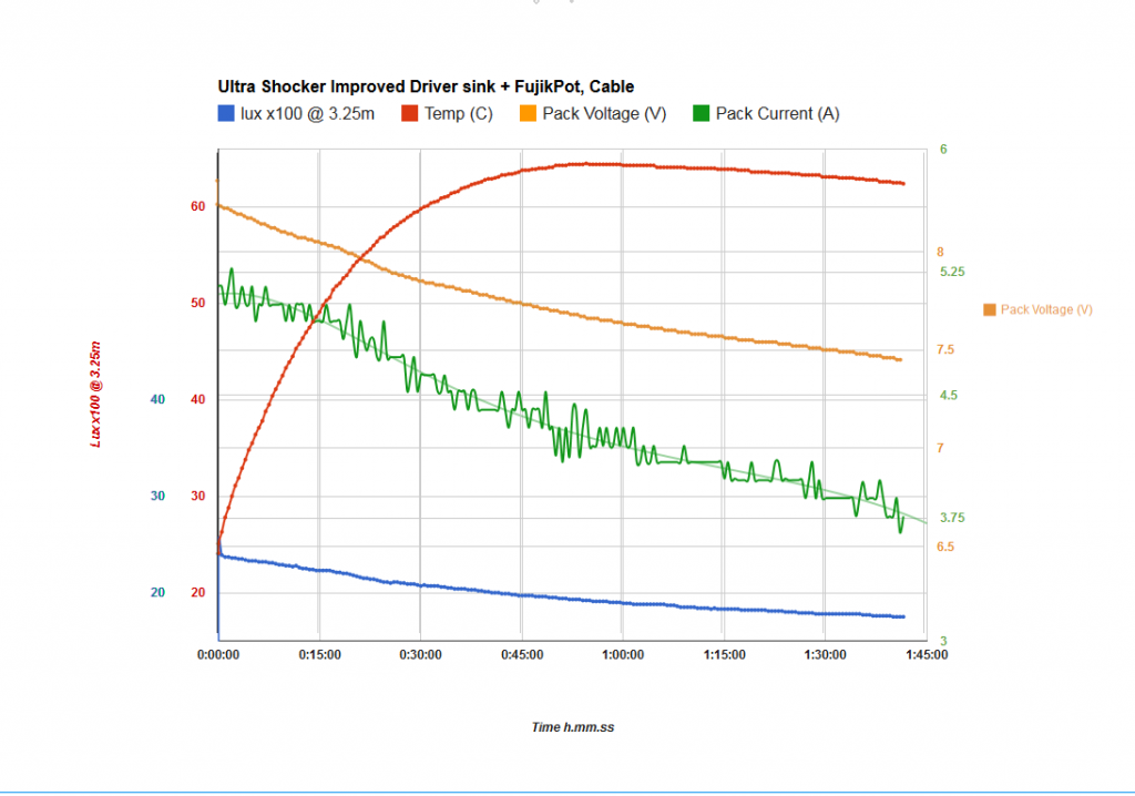
Ok, so after solving my driver temperature issues on turbo I decided to do a long and incredibly annoying 1hr45min test run on medium/high mode (~30% pwm)to see how battery voltage affects the performance at a much more sensible 5A draw current. I wanted to see if the light could dissipate enough heat at this power level to run continuously and to get a clear idea of the voltage overhead that I’m dealing with in the fully assembled light. I still had a niggly feeling that I don’t have a big margin in that regard and had to see just how much of a regulation phase there was without the extreme heat sqewing the results.
The result?…no obvious regulation phase at all…damn! I know it’s not quite ideal to test this under PWM dimming but I believe the regulation and voltage relationships are a fair representation of the light’s behavior under full duty cycle, correct me if I’m wrong here guys.
It’s also clear my current meter is anything but consistent in it’s granular readings (maybe affected by the pwm? however drawing an interpolated line gives me a good idea of whats going on).
Still, even taking that into account it’s not looking right at all. What I expect to see with my projected 0.55v voltage overhead is a consistent regulated drive current at the very least until the battery voltage drops below 8v (theoretically with my estimated drop of ~0.8v it should regulate at max output right down to about 7.7v)…instead I’m seeing a steady drop right from the start that’s more or less in line with the voltage drop at the battery. There may be regulation over the first 10mins but it’s a lot less than I predicted and I’m definitely not seeing a nice flat section anywhere on the current graph.
And this is at a third of the current draw of Turbo mode…voltage loses across the cables should be about a third of what they are at the higher current no?
Ok well I guess I need to spend some more time reducing resistance losses across the light.
-
Obvious places I could improve.
1. Twin power relays in the battery pack (~0.06v @ 17A). I like the idea of having a physical switch to turn power on and off but maybe a mosfet would be better suited to this task. Not to mention the relays use 0.11A just to turn the coils on so that basically negates any efficient long running of the light in moon mode ![]()
2. The Coiled Power Cable (~0.6v @ 17A). There’s obviously massive loses here, even though it’s decent quality copper two core speaker cable, just the coiled nature of the cable means it’s massively longer overall than a comparative length of non coiled cable. I could gain a lot of effeciency here simply by switching this out for a half meter of 12awg silicone wires. The home made coiled cable also isn’t particularly stretchy (especially in sub zero conditions!;)) so the main benefits of this thing are actually cosmetic… :zipper_mouth_face:
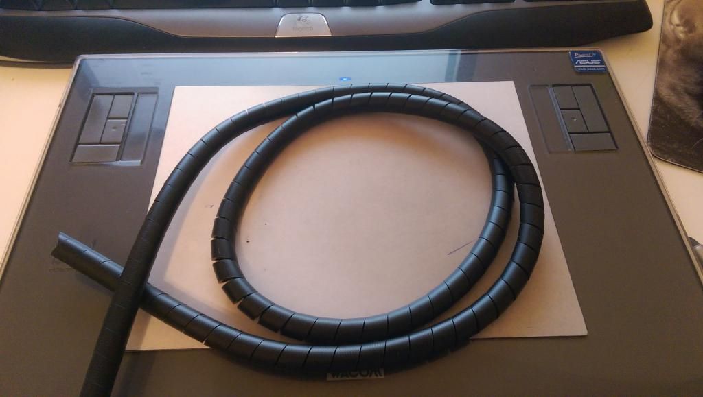
A pair of 12Awg silicone wires encapsulated in this type of thing would certainly be a more sensible option, wouldn’t look to bad either… but I’m still too damn attached to that coiled sucker!
3. Twisty contact interface (??). I’m still not sure how much I’m losing across that interface but this would be the most obvious place for unexpected losses in the power train. The rest is down to the drop across the 7135s and I can’t do anything about that.
—
Edit: Forgot to mention, heat-soaking the light at ~60degrees for close to 2 hours while doing that test has had the positive effect of completely eliminating the moon mode flicker I always had before. I suspect this may be related to the burn-in procedure reported to be beneficial to leds by reducing their vF, in my case moon mode doesn’t seem to be any brighter but it’s much more stable. Yay ![]()
Burn in procedure or fixing the dry solder joint when the solder melted through the heat in the extended run time? l love your persistence.
You know I did hear something sloshing around inside the light after an hour…maybe that was all the solder ![]()
Do you have access to a powerful bench PSU?
On the twisty interface… does the GND spring from your carrier interface with the bare aluminum at the top of the battery tube? If so it all looks pretty good to me… the only thing left to do would be give up on the ability to install a normal carrier. Once you give that up switching to Deans Ultra is a no brainer…
Unfortunately not, that would certainly make testing easier. I do have an iCharger 1000w lipo charger that I could convince to supply a constant voltage/current (using the motor run-in mode). But I’d still need a powerful dc source to make that work, my best source taps out at 90w, unfortunately I left my 1300w converted 24v server PSU in Ireland. ![]()
Hmm, although…thinking about that again I may be able to make it work if I power the iCharger off the Lipos and use it like a boost driver to supply a constant voltage to the light…need to see if it can safely supply 150w at only ~8v input though.
Don’t want to burn anything out on that thing if I can help it, I’ve had some bad experience with lipo chargers in the past going poof when pushed close to their limits in slightly unintended ways.
Edit: According to the manual the charger should be good for an output of 300w at an input voltage of 8v. So I think this is safe to try.
Will report back, hopefully with an output graph at various constant voltages! ![]()
The GND springs are the more robust part of the interface because there are 3 and they’re all making good contact with both the aluminium contact plate as you say but also partially with the edge of the contact board which is directly soldered to the GND supply wire in the head. Everything is additionally clamped together and continuity is good on that I’m fairly certain.
The positive contact point on the other hand is a lone brass stud mating with the center of the 20mm contact board and a recessed second brass stud that’s soldered to the positive driver supply.
If there are losses it’s going to be here I’d say, it relies on pressure more than the others and the mating surface is a lot smaller. I just don’t have a great way of testing this interface with the light assembled as it currently is, wish I’d done this earlier.
I was contemplating doing away with the spring and brass stud on the positive and changing it out for a short beefy 6mm bullet connector. That would still allow the whole thing to turn but make more solid contact.
The bullet connector sounds good, but requires precision unless you soft-mount it somehow I think.
To keep the iCharger happier why not run it from a car battery? I guess it’s cold outside, but the car battery does seem ideal to me.