Wight, I think it’s your fault AR lenses scratch easily. It’s probably even your fault that electronics stink when they burn.
We can blame you for whatever we want to. ![]()
Wight, I think it’s your fault AR lenses scratch easily. It’s probably even your fault that electronics stink when they burn.
We can blame you for whatever we want to. ![]()
That's the spirit! :)
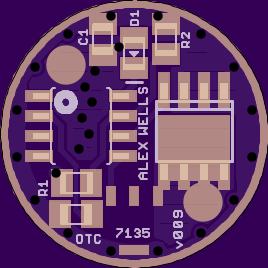
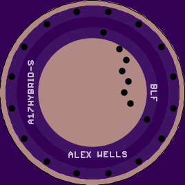
https://oshpark.com/shared_projects/7sNNyipn
v009 changes:
I think what’s left to do at this point is pin down a name and then clean up the sloppy silkscreen on the bottom.
Here’s a WIP screenshot from v008:

Wight, have you had a chance to play with any of the LFPAK33 FETs yet? I ordered some and have a few boards almost done with them, but haven't had a chance to try any yet. I put one on the 15mm version of this board and according to NXP it looks like they are pretty much equivalent to the LFPAK56 FETs.
Heh, frankly I haven’t thought any about them, although as you probably realize I have a couple on hand. I haven’t really shopped to see what’s available. Where it fits I feel like Power-SO8 is the ideal footprint since there are so many options available. It’s a very popular package and no one is likely to be unable to source appropriate parts.
That said, when I re-attack buck circuits I’ll be looking hard LFPAK33 and the other 3.3x3.3 MOSFETs. I can see why it’s a good choice for the 15mm layout.
I forgot to mention this: when I ran the CAM job for v009 I ran both the old and the new job and uploaded both to OSH Stencils. Sure enough, both were off. I think it’s just a flawed setup on their end.
Hmm… How about Mercutio, whose actions brought together two warring houses? Or Defarge or Manette from A Tale of Two Cities?
Well, RMM motivated me: ” 15mm DD+single-7135 driver - single sided Dual-PWM compatible using 3.3x3.3mm FET”:[WIP] *15mm* DD+single-7135 driver - single sided Dual-PWM compatible using 3.3x3.3mm FET
Is there a reason this is still WIP?
I just built one and it appears to work great :bigsmile:
Thanks
Then you built the first one I’m aware of.
Can you post some pictures?
Is everything playing along with the dual PWM? (I don’t see why it wouldn’t.)
As far as I can tell the dual-pwm is working fine.
Moon 2
Low 37
Med 40
with dual-pwm at 38.
Mode spacing appears to be very good set that way. I’ll build another today and post pictures, the first is in a triple XPL 3D Convoy S2 right now.
On this and on some of the DD18 SO8 drivers I am getting a buzzing on the two highest pwm modes, what normally causes that? All of the solder appears solid.
AFAIK the buzzing is something resonating. Tuning your PWM should help eliminate it. Change duty cycles (mode levels), PWM freq, or PWM type (fast/phase correct). The Dual-PWM functionality can split PWM types right in the middle of your mode group if you’d like, that may be able to eliminate the noise at the top end. That’s what’s going on with the “#define FAST_PWM_START”.
Looking forward to pics of your next driver build.
Picture of built driver.
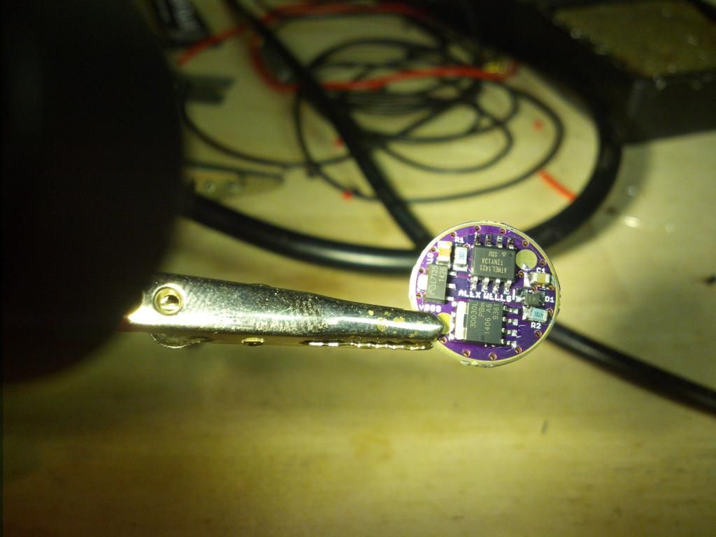
Looks just like it’s supposed to! The SOIC clip fits nicely?
Yes, and I found a pwm setting that gets rid of the buzzing.
Fuses of 0x7a and 0xFF
F_CPU 96000000
Fast PWM above moon.
With the low fuse of 0x75 I was getting the buzz.
9.6Mhz is right on the ragged edge with a protection diode in place. Atmel’s datasheet shows that up to 10Mhz is OK for 2.7-5.5v, but the diode drops around 0.2v or more. So at 2.9v the ATtiny13A sees 2.7v. There may be other considerations that push you over the edge in certain circumstances.
In other words if it’s possible I’d try and stick to 4.8Mhz rather than 9.6Mhz, just to have all your bases covered all the time.
What offtime values are you using and how much time is it taking to save?
I am using the default star offtime values.
In terms of voltage, are you saying I’ll lose the attiny once the voltage drops low enough?
I’m saying that it may malfunction once voltage drops low enough. There will be no damage to the driver, but it’s anybody’s guess what could happen. LVP could fail, that would be my primary concern.
How many seconds does the driver take to save the last used mode?
A mental count of six seconds. Five and it goes to the next mode when turned back on.
Are there magic values for PWM and 4.8 to have no buzzing? My medium at 40, and high at 125 buzzed at 4.8 and fast pwm.
No magic values AFAIK. Resonant freq depends on hardware, variables. You’re using Fast PWM?
EDIT: I forgot to address the offtime thing. Crank it to around 240 and see about that. Generally nice offtime should be memorizing things in <1s IMO.