Yeah, right! Seems strange not to include something like that in a datasheet for a device that’s almost invariably going to get really hot, just by it’s nature of being a linear controller.
—
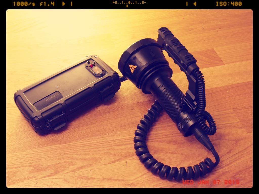
The blower fan I ordered a while ago finally arrived today, so I sellotaped it to the light and re-ran a couple tests to see how things stack up with active cooling.
The plan was to direct all of the airflow from the blower over the majority of the meager heatsink fins available on the BTU. I just did this with electrical tape for now, keeping the airflow contained and running between the fins top and bottom then leaving through an exhaust port on the opposite side.
The fan is designed for 12v so it doesn’t quite run as fast as I’d hoped, but it still shifts some decent air and makes quite a racket on 8v. ![]()
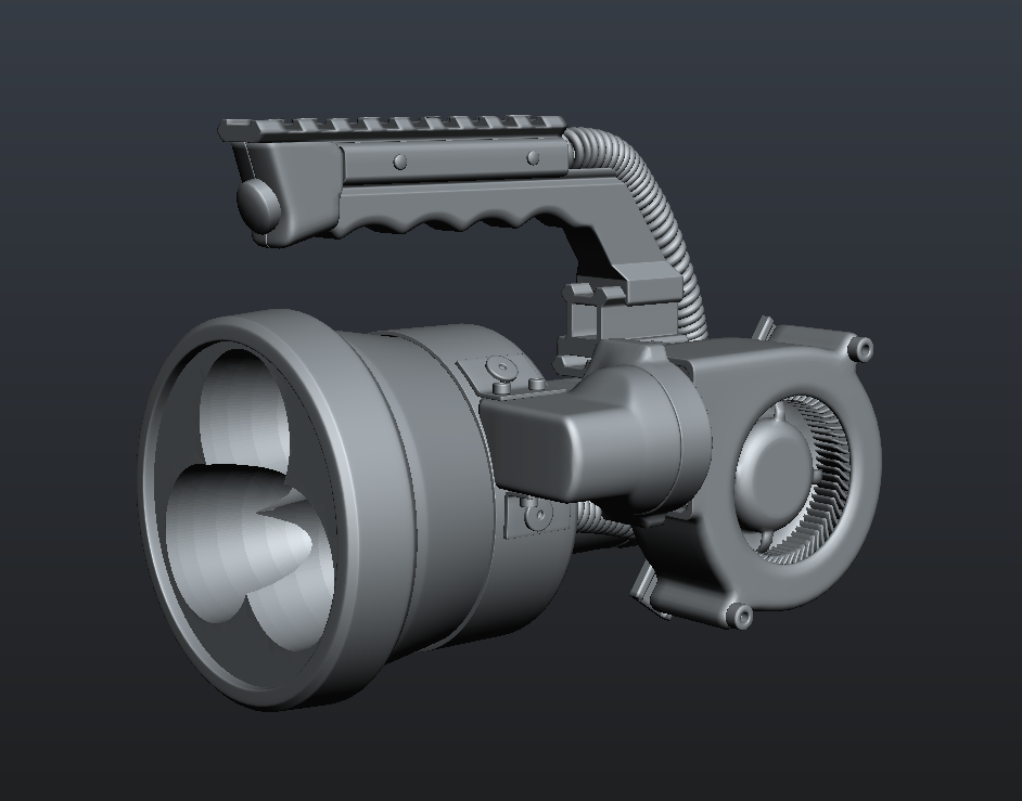
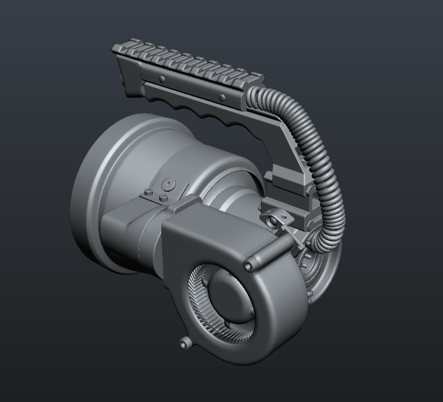
Ultimately I think I’ll mount the blower flush on the side of the battery tube and fashion some kind of a 90degree duct to redirect the airflow through the fins. All mounted on a removable modular picatinny rail setup of course. Maybe even make it temperature controlled if I can be bothered. ![]()
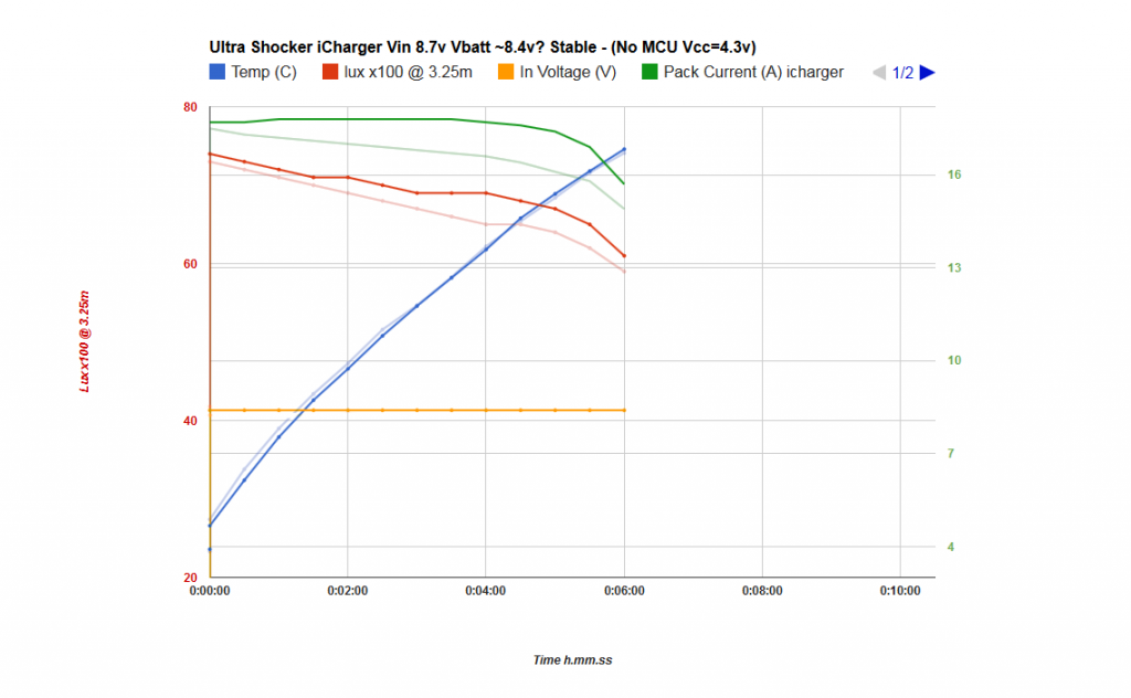
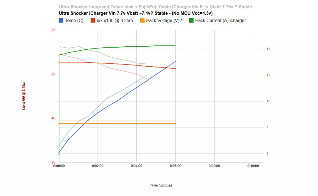
The following graphs are simple reruns with the blower on full compared against the previous tests. Most obvious difference is I could easilly run the test to 10mins before getting worried about heatsking temps exceeding 70degrees.
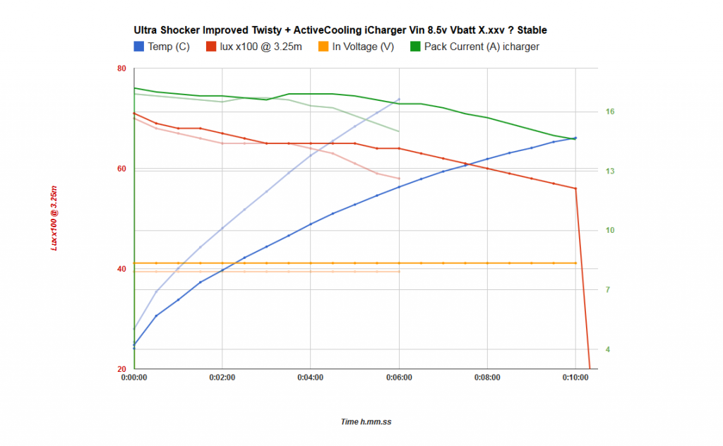
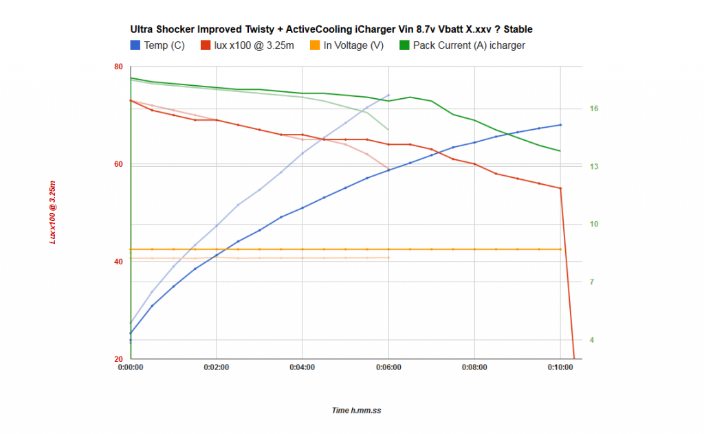
Nothing too surprising here, although I was hoping to see some plateauing of the temperature at some point, guess I need two fans after all. ![]()
It’ll probably keep up better when the light is running off batteries.
Also of note is that a much lower heatsink temperature seems to only really affect the drivers, ie by delaying the heat related behaviour where they drop output current. The leds don’t seem to produce noticeably higher output at these lower temperatures and are primarily handicapped by the drivers throttling back drive current.
Although granted I don’t trust my light meter readings between tests enough to show subtle differences in output regarding temperatures at the leds. Sometimes it can be as much as 5klux out at turn on and when I compensate the graphs to match performance at the same drive current draw they line up perfectly again.
I’d need a decent integrating sphere to really see what differences in output actually are.
—
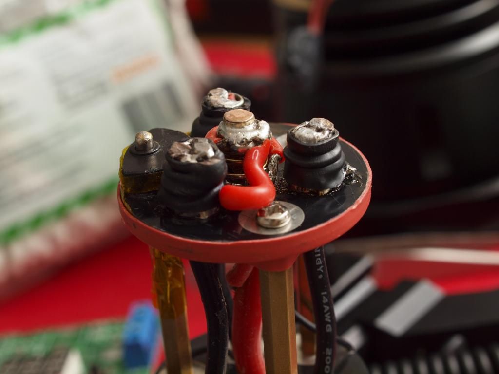
I also decided to go resitance hunting and started by reinforcing the twisty interface contacts a bit. Just for peace of mind and to see if I could gain any noticeable voltage overhead there. The contact pressure had declined slowly since I made the thing and that was bugging me, it was nice and tight to begin with but with all the testing and reopening/closing and general wear it wasn’t quite as reassuringly tight as it was. The springs where still springy but the tolerances had just opened up some in general.
The positive path also needed a bit of beefing up and improving to put my mind at ease ![]()
I added an small disk of copper to the top of the positive brass post to increase the height a bit, then ran an additional length of 16awg wire through a hole in the carrier disk and soldered it directly it to the thick positive wire coming from the connector. I also jammed some spare silicone tubing under the spring to ensure contact pressure was really high for a solid connection.
The negative posts were also overhauled a bit and I replaced copper braid in two springs (which had started failing) with 18awg wires. These should make good contact.
Ultimately as a result of all this I almost couldn’t tighten down the battery tube, the contact pressure and friction was considerably higher than before…and the positive post showed a nice polished arc where it mated with the brass recess on the contact board! Great
I ran tests at 8.5 and 8.7v after all this and compared against the before graphs, that showed no noticeable improvements at all…nothing! The bumps and dips on the current readings all lined up and so did everything else, so little difference in fact I won’t even bother posting the graphs.
A bit disappointing but I think it’s safe to say the contacts where likely good enough to begin with and I can at least rule this out as a major resistance bottleneck in the light.
—
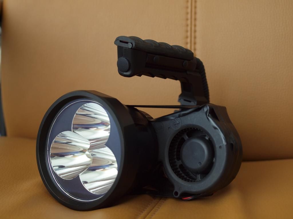
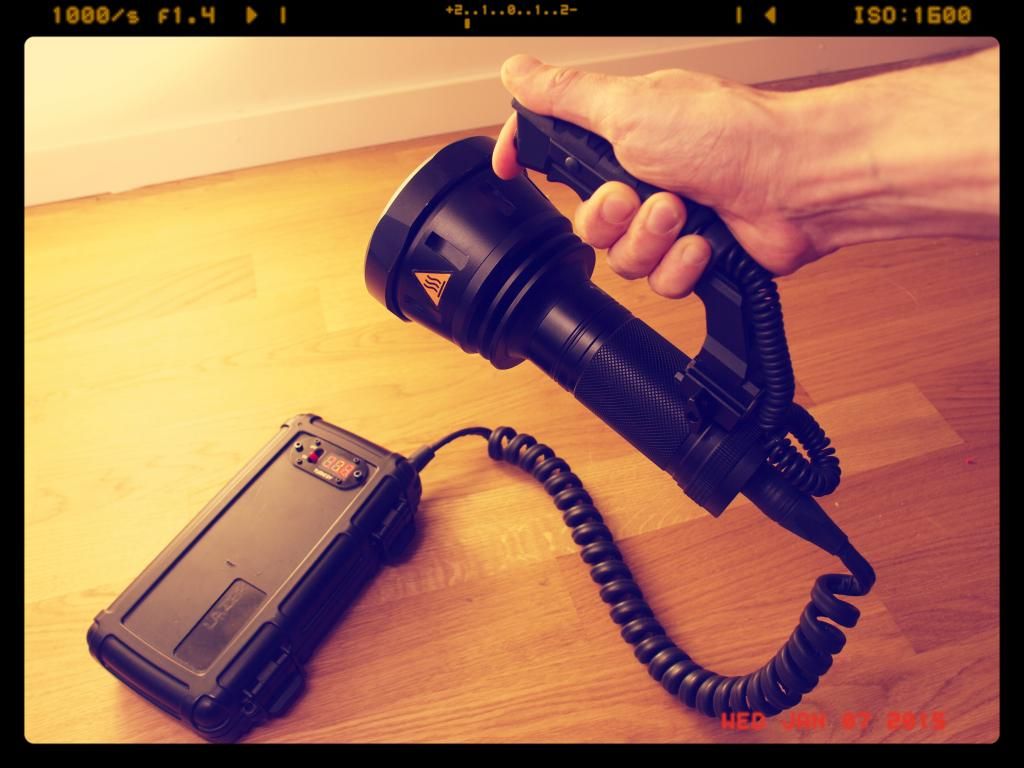
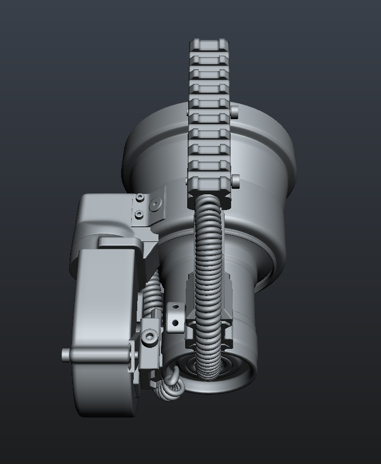
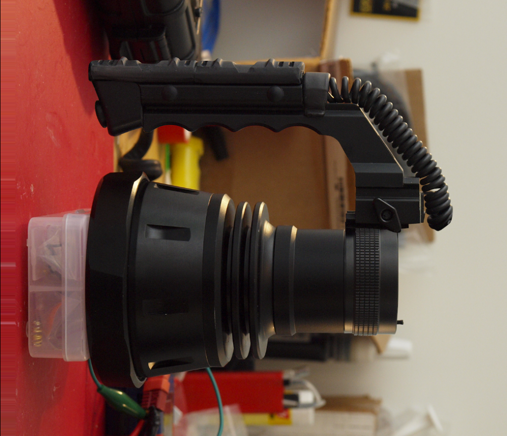
Finally just a couple shots of the whole light after a hard day strapped into the test apparatus. 8)
Shows how it sits in the hand as well. It’s really a very comfy grip once you get used to the unnatural weight of the thing ![]()
 If so this would greatly increase the density in the battery increasing efficiency and greater lumen output.