Thanks. I was notified that mine were sent to the fabricator the same day I ordered them, I just didn’t know how long it takes from there.
I know the feeling, I ordered mine on Dec 28th, shipped Jan 8th so hopefully they’ll be here soon.
It’s sad having all the components on hand but no boards in sight. ![]()
I just got my shipping notification. 3 each of the 20mm and v06 17mm. Exciting stuff! I hate the look of all the 7135’s stacked, so hopefully this will be the solution. :party:
You say you hate the look of stacked chips, have a look at this board and tell me which ones are stacked….one is the moon mode, the others are the rest of the modes. Wights PZL driver.
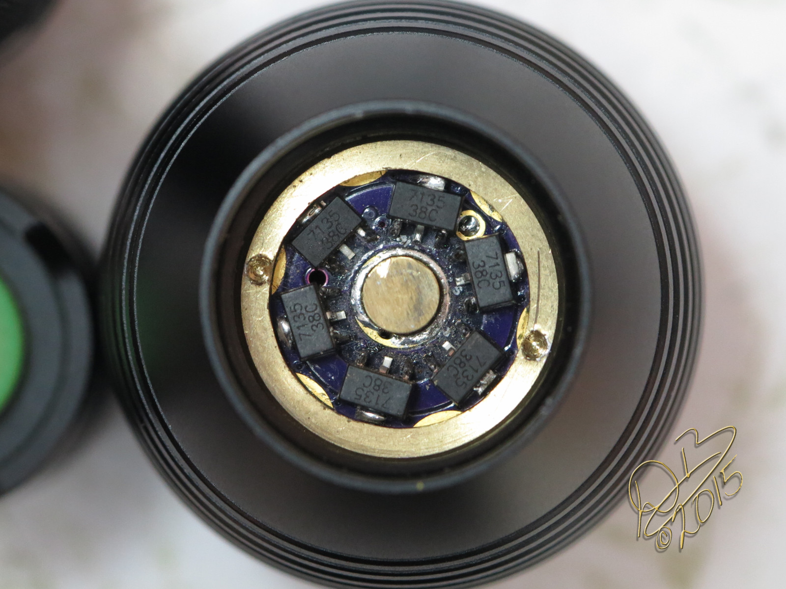
Love how this looks in the tube when changing cells! ![]()
That PZL has 15 chips, keeping it’s MT-G2 to a respectable 5.43A for 2500 lumens. And yes, that’s an Eagle Eye X6.
All of Wight’s boards are easy to assemble, with oversized pads and a nice layout that makes even hand soldering a piece of cake. ![]()
I’ll take a guess! The top left corner is not stacked.
a deeper pill with a retaining ring like the x6 makes it look fine, but sticking out the bottom of a P60 is ugly to me.
I sat there and looked at it, very pleased with how well the stacked ones blended in. Really it only shows in that center leg that isn’t soldered. The stacked ones show the center leg bent down. ![]()
I hear ya, whenever possible I used to do all the stacking on the inside. Seems like I had 22 chips on a board before. Chips everywhere. No Coke, Pepsi….
My boards were delivered today. You recommend 22.1 for R1?
IIRC I’ve been recommending 22k (22,000).
Don’t forget that you’ll need to significantly drop the PWM freq for this thing to work correctly. The last test I did was at ~1khz I think. I switched the firmware to Phase Correct PWM and used the :8 divider as per post #51 in this thread.
The divider should look something like this:
TCCR0B = 0x02; // pre-scaler for timer (1 => 1, 2 => 8, 3 => 64...)
I’m sure it hasn’t been tested, but do you have any expectation for what parasitic drain might be if used as momentary?
Mostly acceptable with 1s, not acceptable with the Zener installed (2s / MT-G2 etc).
I would just be using 1 cell. You think it would be about the same as a 105c?
Yes, that is my expectation.
I’m still waiting on my OSHpark boards so I’ll be keeping a keen eye on how your testing goes!
Cheers
I plan to build it tonight after work. I’m still a novice at all of this, so if I have any issues you can be sure it will get posted here!
With the PWM frequency at 1 Khz, what do you see on the output? Is it still pretty smooth? I still find it intersting that the 9.4 kHz runs so well in the M6, but it's got to have something to do with the component network that feeds the 7136 its PWM signal.
I also have not found the parasitic drain to be objectionable.
In STAR Momentary, do the ALT_modes need to match the regular modes? Or do I just comment them out?
The ALT_modes are for the ALTernate, or secondary PWM out. If you're only using a single PWM output, then leave them commented out.
Right, so does this driver use the ALT, or just the primary? Sorry, my question wasn’t clear.
You can see that the PWM output is on Pin 6, so the normal output is what is being used.