Was delighted to see the 7136s chips finally get here today, so I built up a test board and did a bit of testing.
Build report:
A self inflicted nightmare of epic proportions. I won’t get into too many details but it was pure frustration, nothing at all to do with the design of the board really. Just…I really miss having a hot air gun. 
-
Then I forgot that this board actually has a trace for Turbo bypass and needs a firmware tweak to actually turn on regulation. Running stock STAR Offtime the thing is constantly in some kind of direct drive! So be warned!
Of course that didn’t click with me until after I had melted a couple sense resistors and blown one of my long suffering test XMLs to smithereens :_(
I remember Wight saying something about putting the Bypass pin into High impedance mode or something, but at that stage I couldn’t be bothered to figure out how to change it in firmware so I just cut the Trace and continued along my merry way.
Regulation was then working fine until the light was on high for more than a few seconds…then it just turned off. Some components get quite hot so I figured something went poof, but no all was fine. MCU pwm looked normal, sense resistor still there…all looked fine except the 7136 was no longer outputting anything. Damn must have killed it, maybe my crappy frustrated soldering?
I ended up replacing the 7136 3 times thinking I’d heat damaged it and it was dying prematurely on me. A few seconds on high and all would go dark.
Turned out it was a patch of unmelted solder paste underneath the mosfet that would partially short out the gate pin once the thing got up to temp…urgh!
This is why I like my mosfets nice and big! Haha 
-
Alrighty, so after all that mess here goes the first batch of testing.
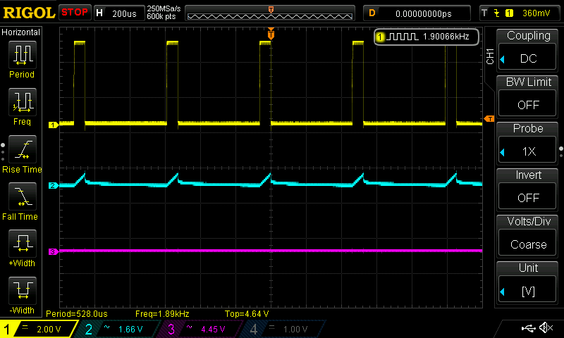
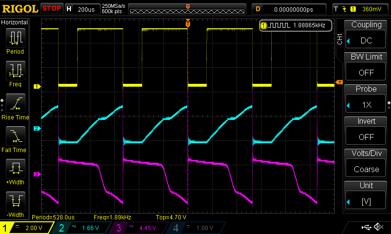
I wanted to get to the bottom of why frequency has such a drastic affect on the pwm performance of the driver so I hooked up my Rigol and went to town.
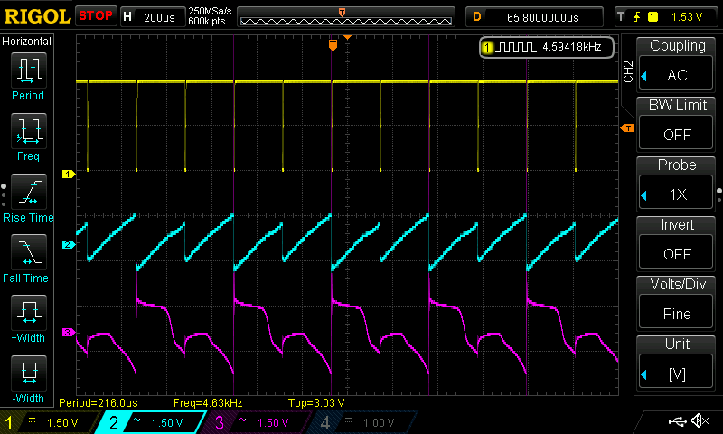
I probed the MCU pwm output (Channel 1), the 7136 output/gate signal (Channel 2) and the drain output of the mosfet (Channel 3).
Note: Ch2 and 3 are AC coupled so they jump around a bit, should have locked them down with DC but hey, I’m new at this scoping business
In any case it’s the shape of the curves that matter not the absolute measurements here I think.
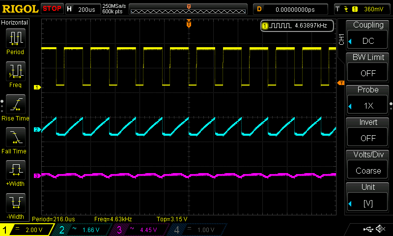
Here is what things look like at 1khz: i.e Phase correct / 4.8Mhz / 8x divider
PWM: 30 - No light, with warm leds very very dim moon mode
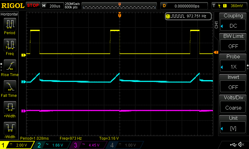
PWM: 60 - Low output
PWM: 100
PWM: 180
PWM: 255 (Just for good measure)
So as expected things work ok at 1khz. And it’s also clear to me what the issue is here.
The 7136 shows a very clear ramp up behaviour on it’s output, it’s pretty slow and even at 1khz it only manages to fully turn on it’s output during a cycle when it’s set to 100 pwm or higher. Anything below that it’s going to start ramping up but then get’s cut off. That has a knock on effect on the mosfet, which also takes some time to get up to speed. At 30pwm you can see the 7136 start ramping up a fair way but it’s not enough to make any real impact on the mosfet so the leds stay dark.
Usable Range: 30-255
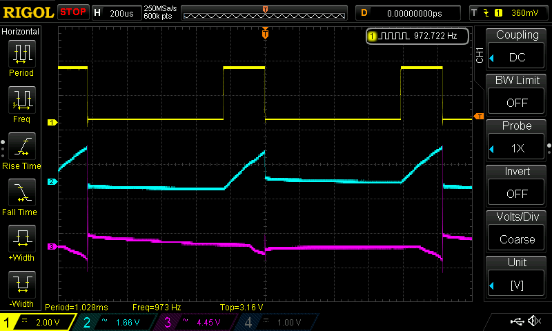
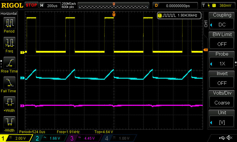
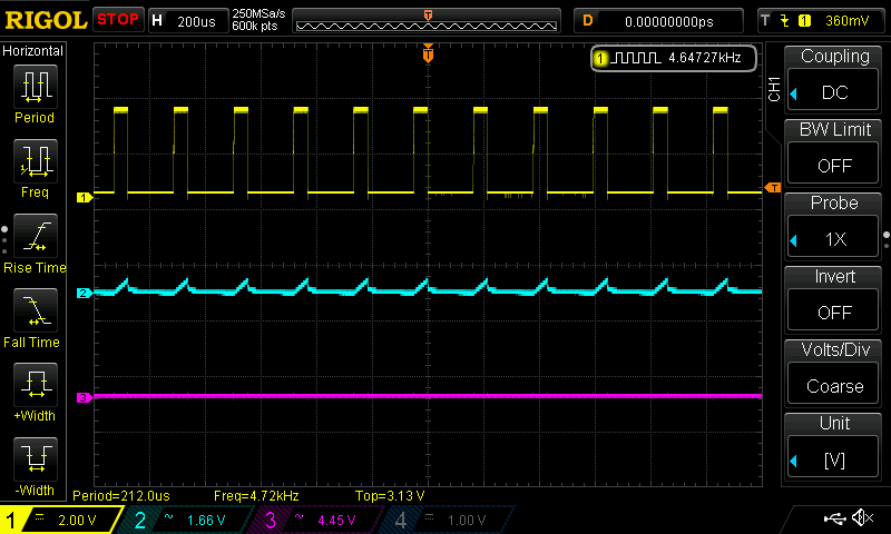
2.4 khz i.e Fast PWM / 4.8Mhz / 8x divider
PWM: 30 - No light
PWM: 60 - Barely on Moon mode, very very dim
PWM: 100
PWM: 180
PWM: 255 (Just for good measure)
It’s clear to see the PWM range compression taking place as the frequency ramps up, a moon mode at ~60pwm also matches up well with what pilotdog68 reported seeing. This is at 2.4khz and I think still a good usable range, unfortunately PWM flicker is still apparent at this frequency. Better than 1khz for sure and you have to look for it but it’s definitely still there. Sweeping your eyes back and forth quickly reveals the evil flicker 
Usable Range: 60-255
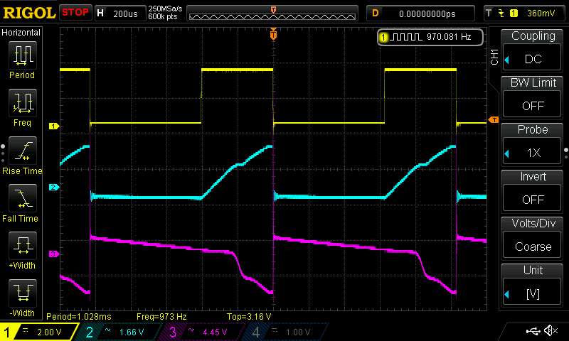
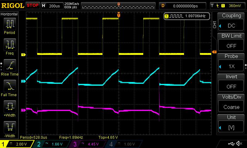
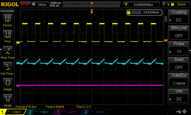
Hoping for a still usable range with less visible flicker I reran the test at 4.7khz i.e : Fast PWM / 9.6Mhz / 8x divider
———————————————————————————————————————————————————————-
PWM: 30 - No light
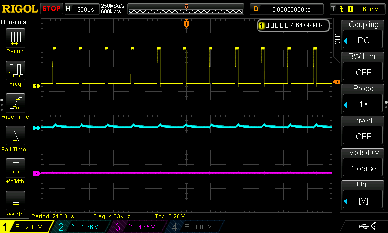
PWM: 60 - No light
PWM: 100 - No light
PWM: 180 - Yay a few stray photons - A dim but usable moon mode
Ahem, well that’s not great is it. Moon mode at 180pwm!
That said I need to test a bit more and see if this is enough of a PWM range to get some usable spacing on the modes. I suspect it may be workable with some specific mode picking. Also by looking at that one moon mode, I can’t detect any flicker at this speed. Maybe it will still be obvious with higher output but I’m optimistic.
“Usable?” range 180-155
Edit: Nope not a usable range at all. It’s all moon modes until you hit 255. Even 253 is very dim, like dim enough to look directly at the led… dim
Also some really funky stuff happens to the mosfet waveform at this stage.
Yuck!
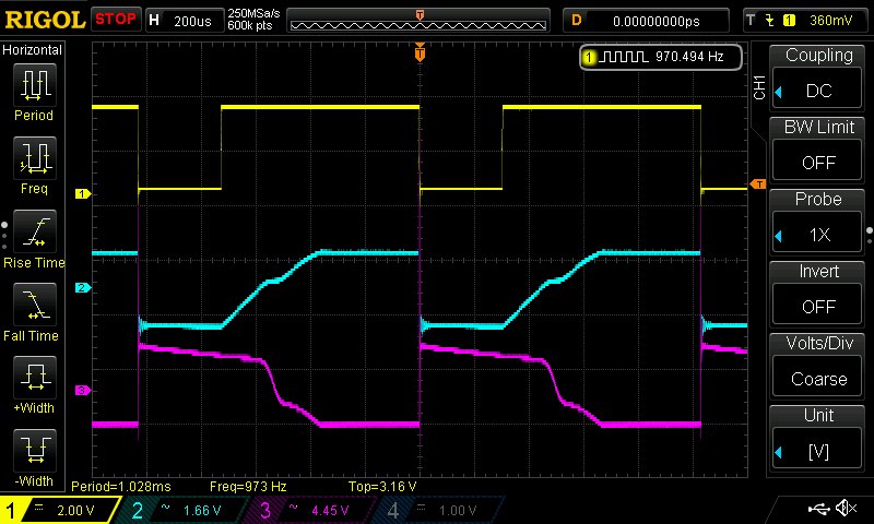
Finally I wanted to know exactly what the components do on a 0-100% turn on and how long everything takes to settle into place. Fairly tricky to capture actually, since I was using a clicky and if simply left to bang on it leaves some godawful noise on the waveforms. Gently does it! 
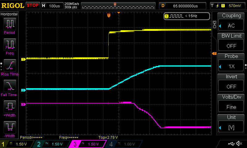
Looks to me like the 7136 takes almost exactly 300uS to ramp up to fully on and the mosfet has a delay of another 150uS after the start of the ramp before it does anything.
I’m still not sure how threshold voltage, gate charge, gate resistance or timing characteristics play into this behaviour but this looks like a very good method for finding out!
Anyone want to send me a spare DNT30N02 to compare? :bigsmile:
In the meantime I think I’ll just slap a couple of random mosfets on there and see how they respond, then cross check to see what specs may be contributing to those differences.
Fun times